HF Circuit .pdf - 第280页
6 - 5 0303805 8-010 101XD 0 P neumati c unit, SIP LAC E HF seri es, connec ting diag ram, Q MH23 p rofile (S h. 2 of 3) Placem ent circu it + ret urn m otio n cylin der 4.5 ± 0.1 bar, 50 st.l /min. Pla cement circu it Re…
6 - 4
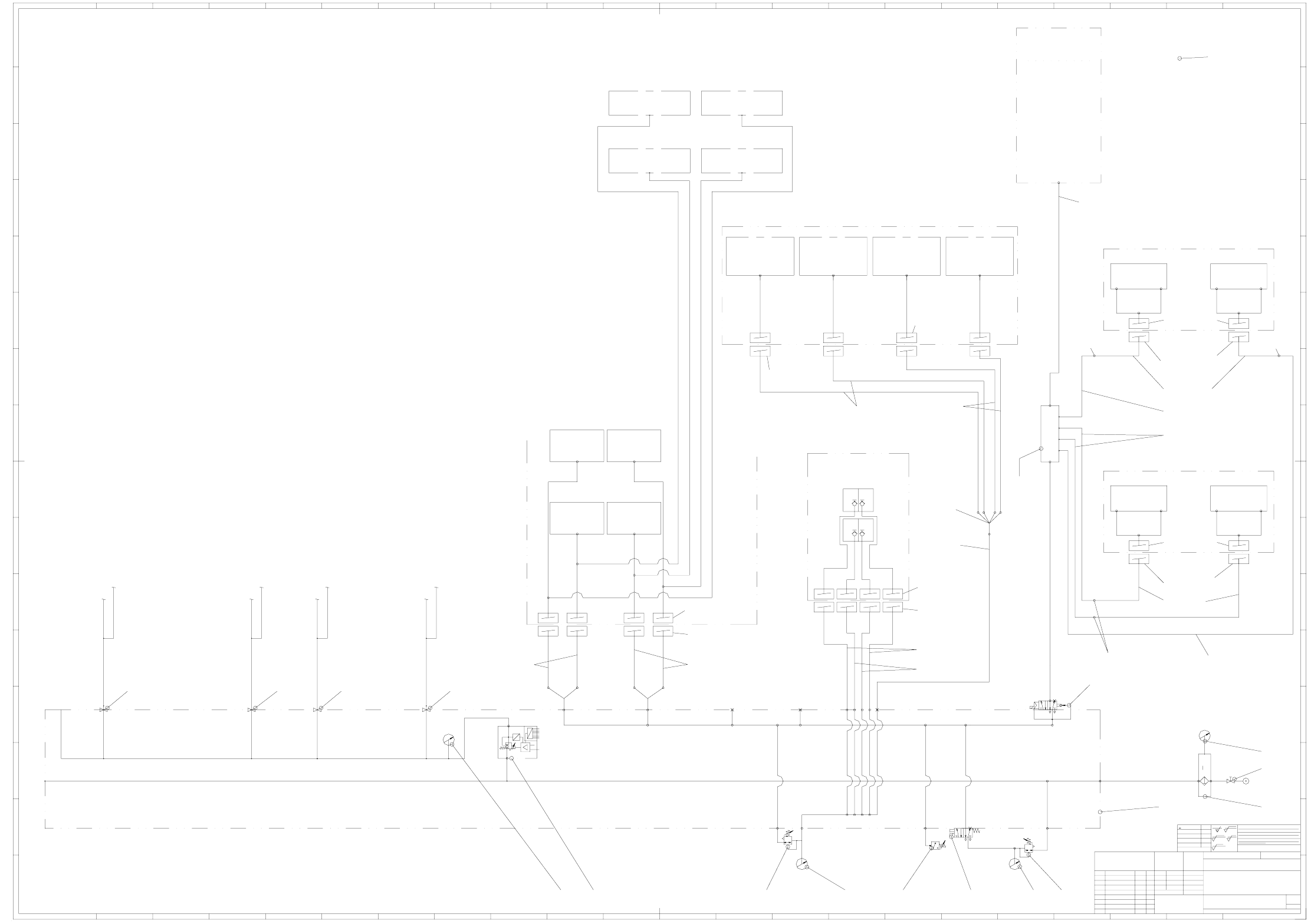
03038058-010101XD0 Pneumatic unit, SIPLACE HF series, pneumatic system (Sh. 1 of 3)
9070 7050 40
60
30
PUN 6 x 1.00 (2.0m)
03006585-xx
PUN 6 x 1.00 (1.8m)
03004146-xx
PUN 4 x 0.75 (2.2m)
03006583-xx
PUN 4 x 0.75 (2.0m)
03004143-xx
PUN 6 x 1.00 (0.4m)
03006589-xx
PUN 4 x 0.75 (1.6m)
03004145-xx
PUN 4 x 0.75 (1.9m)
03006588-xx
Interface
Compr. air supply, dock. unit
03004200-01
Interface, CO dock. unit
(Sockets)
03004679-xx
Interface, CO dock. unit
(Sockets)
03004679-xx
Interface, CO dock. unit
(Sockets)
03004679-xx
Interface, CO dock. unit
(Sockets)
03004679-xx
03038692-xx
03039851-xx
Hose connection
RTU-PK-4/6
00047026-xx
Hose connection
RTU-PK-4/6
00047026-xx
Interface
Compr. air supply, dock. unit
03004200-01
Hose connection
RTU-PK-4/6
00047026-xx
= Item no. Siemens parts list (Cadim)
03038355-xx
10
10
Multiple distributor
QSQ-6-4
00336911-xx
See sheets 2 and 3 See sheets 2 and 3 See sheets 2 and 3 See sheets 2 and 3
otherwise s pecified
Repl. f.
SP = location
140140 140 140
110/120
70 500/300/310 80
100
Consumption not relevant
Feeder unlocking rail
SP 2
Consumption not relevant
Feeder unlocking rail
SP 1
Consumption not relevant
Feeder unlocking rail
SP 3
PUN-4 x 0.75
PUN-4 x 0.75
PUN-4 x 0.75
Consumption not relevant
Feeder unlocking rail
SP 4
PUN-4 x 0.75
5um
p = 5.0 ±0.25 bar
Trolley dock. unit
03000811-xxxxxx
SP 3
Consumption not relevant
Do not operate during placement operation
Trolley dock. unit
03000811-xxxxxx
SP 2
Consumption not relevant
Do not operate during placement operation
Trolley dock. unit
03000811-xxxxxx
SP 4
Consumption not relevant
Do not operate during placement operation
Trolley dock. unit
03000811-xxxxxx
SP 1
Consumption not relevant
Do not operate during placement operation
PUN 8 x 1.25 (xxxm)
03004138-xx
Modular single conveyor
00119625-xx
Modular dual conveyor
00119627-xx
max.255 st.l/min.
Lifting table 1
Lifting table 2
Lifting tables 3 and 4
in dual conveyor system
Width adjustment
Consumption not relevant
PCB stopper (option)
Consumption not relevant
255 st.l/min.
Ceramic substrate centering
(Option)
DC SIPLACE HF, 00119670-xx
SC SIPLACE HF, 00119671-xx
p = 2.5 ± 0.5 bar
X58
Proportional valve
p = 5.0 ±0.1 bar
X
V
P
D
A
external
internal
NOM value
8 bit
digital
Adjust at internal potentiometer
Pressure required
p = 4.6 +0.1 bar
PUN 8 x 1.25 (1.2m)
03006587-xx
PUN 8 x 1.25 (1.0m)
03004147-xx
PUN 8 x 1.25 (1.2m)
03006587-xx
PUN 6 x 1 (0.3m)
03004677-xx
PUN 6 x 1 (0.3m)
03004677-xx
Schönbach07.03.05
Pneumatic unit, Siplace HF series
Pneum. system
03038058-010101XD0
max.50 st.l/min.
)(
A0
2-5 um layer (nickel-plated)
1
3
Degree of accuracy
DIN 7167
A&D
<6
>6...30
>30...120
>120...400
>400...1000
±0.1
±0.2
±0.3
±0.5
±0.8
z
R 100
z
R 25
z
R 6.3
z
R 1
22
K
I
H
G
F
E
D
C
B
A
15141312111098765432
Weitergabe sowie Vervielfältigung dieser Unterlage, Verwer-
tung und Mitteilung ihres Inhalts nicht gestattet, soweit nicht
ausdrücklich zugestanden. Zuwiderhandlungen verpflichten zu
Schadenersatz. Alle Rechte für den Fall der Patenterteilung
oder GM-Eintragung vorbehalten.
Copying of this document, and giving it to others and the use
or communication of the contents thereof, are forbidden with-
out express authority. Offenders are liable to the payment of
damages. All rights are reserved in the event of the grant of
a patent or the registration of a utility model or design.
1 16 17 18 19 20 21 22
151413121110987654321 16 17 18 19 20 21
L
M
N
O
P
R
K
I
H
G
F
E
D
C
B
A
L
M
N
O
P
R
She et
Sh.
Material
Format
Drawing no. (FS RS DS DT L F)
Sca le
Stand.
Check.
Author
Date N ame
case hardened
HRc tempered
Surface.:
Dime ns. varia tions
NameDateModification / ECO no.
Siemens AG
General tolerances
for nominal dimensions as per
ISO 2768 mH, unless
ECR no.
Schönbach08.03.05
1/4" 5 x M51/8"
1/4"1/4"1/2"1/2"1/2"1/2"1/8"
3/4"3/4"
Main hole >3/4"
X
Valve block
X
X60
2
3
4
1
5
Safety valve
255 + 138 st.l/min. PUN 10
Distributor
V5e1
PUN-6
PUN-6
Interface
Compr. air supply, dock. unit
03004200-xx
PUN-6
PUN-6
SP 3
max. 138 st.l/min.
Tape cutter
03019941-xxxxxx
4.5 bar 4.5 bar
SP 4
max. 138 st.l/min.
Tape cutter
03019941-xxxxxx
PUN-6
PUN-6
Interface
Compr. air supply, dock. unit
03004200-xx
PUN-6
PUN-6
SP 2
max. 138 st.l/min.
Tape cutter
03019941-xxxxxx
4.5 bar 4.5 bar
SP 1
max. 138 st.l/min.
Tape cutter
03019941-xxxxxx
Press. switch
X59
X59
Main valve
bA
2
3
4
1
5
A0
Interface
Compr. air supply, dock. unit
03004200-xx
SP 3
Nozzle changer (option)
(12-seg. C&P 03001855-xx
6-seg. C&P 03004010-xx
C&P20)
up to max. 2 per SP
Consumption not relevant
2.5 bar
2.5 bar
PUN-4 x 0.75
PUN-4 x 0.75
2.5 bar
2.5 bar
PUN-4 x 0.75
PUN-4 x 0.75
Cover up connections in HF machines
SP 4
Nozzle changer (option)
(12-seg. C&P 03001855-xx
6-seg. C&P 03004010-xx
C&P20)
up to max. 2 per SP
Consumption not relevant
SP 2
Nozzle changer (option)
(12-seg. C&P 03001855-xx
6-seg. C&P 03004010-xx
C&P20)
up to max. 2 per SP
Consumption not relevant
SP 1
Nozzle changer (option)
(12-seg. C&P 03001855-xx
6-seg. C&P 03004010-xx
C&P20)
up to max. 2 per SP
Consumption not relevant
SP 2
SP 3
max.50 st.l/min.
SP 4
SP 1
Bulk case feeder connection
(Option)
Interface
Compr. air supply, dock. unit
03004200-xx
Air consumpt. line for machine modules
443 st.l/min.
B23.3B23.2
B23.1
B23.4
B22
Gantry 4
Gantry 1 Gantry 2
Gantry 3
p = 5 to 10 bar
at an air consmpt. of 1800st.l/min.
B13.2
B13.1
B1
B11
B9
B10.4
B10.3
B10.2
B10.1
B7 B8
B6
Air consumpt. SIPLACE HF heads
300 st.l/min (1xC&P6/12; 1xTH) or
400 st.l/min (2xC&P6/12) or
800 st.l/min (4xC&P6/12)
B2
B3
B4
B5
B14
B20
B13.2B13.2
B21
S1
M1
M2
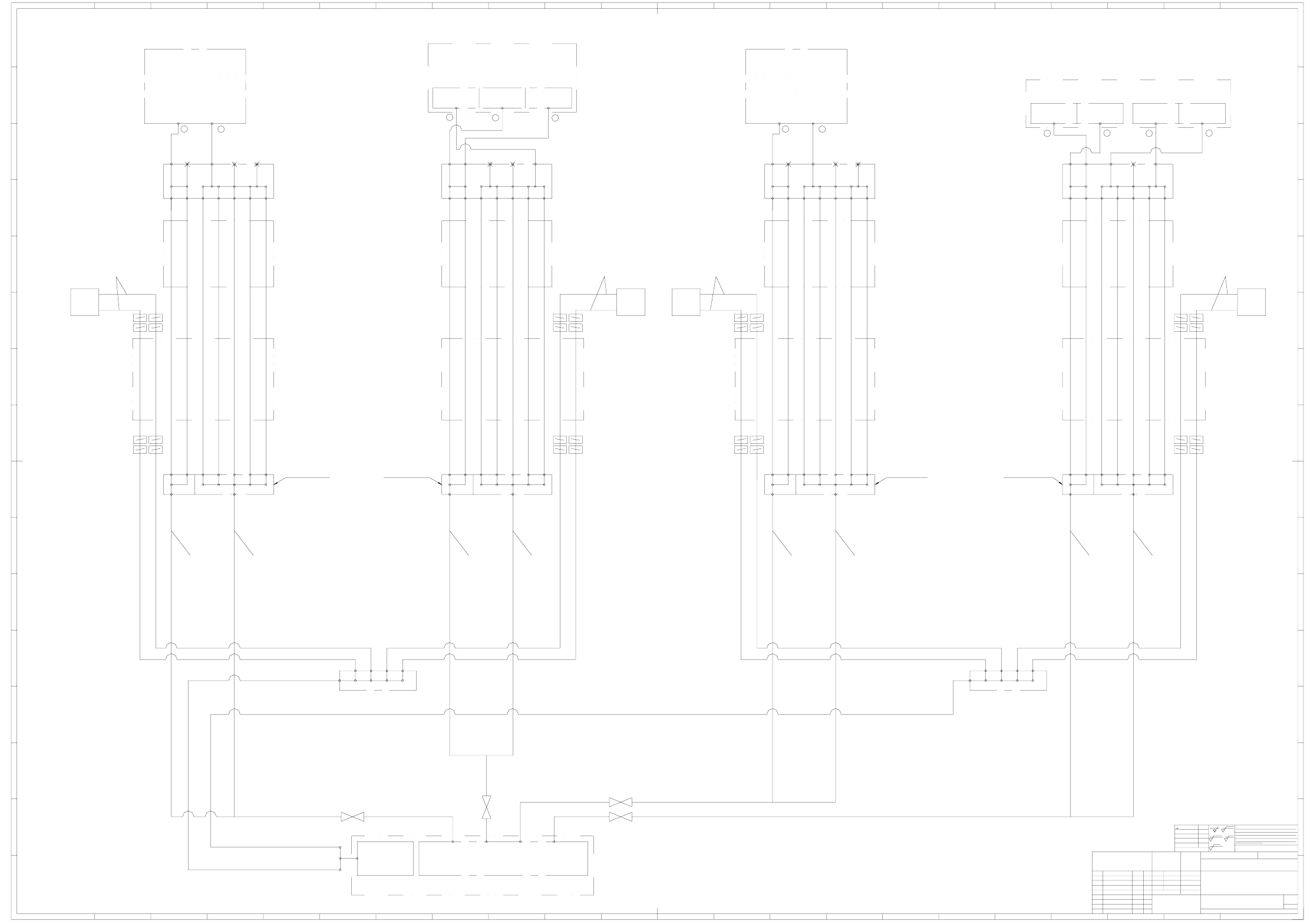
6 - 5
03038058-010101XD0 Pneumatic unit, SIPLACE HF series,
connecting diagram, QMH23 profile (Sh. 2 of 3)
Placement circuit + return motion cylinder
4.5 ± 0.1 bar, 50 st.l/min.
Placement circuit
Return motion cyl.
Holding circuit
2.5 - 4.5 bar, 120 to 200 st.l/min
2
1
Holding circuit
C&P20 head
3
X cable and hose carrierX cable and hose carrier X cable and hose carrier X cable and hose carrier
Y cable and hose carrier
QMH23 profile
Y cable and hose carrier
QMH23 profile
Y cable and hose carrier
QMH23 profile
Pneumatic hose 03005790-xx
TUS1208 Soft PU 12x8 ( 0.32m )
Pneumatic hose 03005790-xx
TUS1208 Soft PU 12x8 ( 0.22m )
Pneumatic hose 03005790-xx
TUS1208 Soft PU 12x8 ( 0.32m )
Pneumatic hose 03005790-xx
TUS1208 Soft PU 12x8 ( 0.22m )
Pneumatic hose 03005790-xx
TUS1208 Soft PU 12x8 ( 0.25m )
Pneumatic hose 03005790-xx
TUS1208 Soft PU 12x8 ( 0.25m )
Pneumatic hose 03005790-xx
TUS1208 Soft PU 12x8 ( 0.25m )
Y motor
Y motor
Y motor
Pneumatic hose 03005790-xx
TUS1208 Soft PU 12x8 ( 0.25m )
Y cable and hose carrier
QMH23 profile
Y motor
Cooling air distributor, X series
03005409-xx
Ø 12Ø 12Ø 12Ø 12
Cooling air distributor, X series
03005409-xx
Ø 12Ø 12Ø 12Ø 12
Gantry 4Gantry 3Gantry 2Gantry 1
PVC hose with woven fabric inlay, Ø 16x4
PVC hose with woven fabric inlay, Ø 16x4
Fan unit
(Elmo)
03006294-xx
Pneumatic unit, Siplace X series
03038058-xx
Valve block, SIPLACE X series
03038355-xx
V1e1
Gantry distributor cpl.
03004080-01
V1e2
V2a1
V2a2
V2a3
V2a4
V2a5
V2a6
V2a7
V2e2V2e1
22
K
I
H
G
F
E
D
C
B
A
151413121110987654321 16 17 18 19 20 21 22
151413121110987654321 16 17 18 19 20 21
L
M
N
O
P
R
K
I
H
G
F
E
D
C
B
A
L
M
N
O
P
R
>400...1000
<6
>6...30
>30...120
>120...400
±0.1
±0.2
±0.3
±0.5
z
R 100
z
R 6.3
z
R 1
2-5 um layer (nickel-plated)
case hardened
HRc tempered
Surface.:
()
Dime ns. varia tions
±0.8
z
R 25
ECR no.
Drawing no. (FS RS DS DT L F)
Pneumatic unit, Siplace HF series
03038058-010101XD0
Degree of accuracy
General tolerances
for nominal dimensions as per
ISO 2768 mH, unless
otherwise specified
Siemens AG
Modification / ECO no. NameDate
DIN 7167
Stand.
Check.
Author
Connecting diagram, QMH23 profile
A&D
Repl. f.
Schönbach07.03.05
NameDate
Scale
Material
3
2
She et
Sh.
Format
A0A0
Copying of this document, and giving it to others and the use
or communication of the contents thereof, are forbidden with-
out express authority. Offenders are liable to the payment of
damages. All rights are reserved in the event of the grant of
a patent or the registration of a utility model or design.
Weitergabe sowie Vervielfältigung dieser Unterlage, Verwer-
tung und Mitteilung ihres Inhalts nicht gestattet, soweit nicht
ausdrücklich zugestanden. Zuwiderhandlungen verpflichten zu
Schadenersatz. Alle Rechte für den Fall der Patenterteilung
oder GM-Eintragung vorbehalten.
(1.9m) (2.5m)
Hose 03012081-xx
made of
TFU0604B-8-10-X17 (SMC)
Hose 03012081-xx
made of
TFU0604B-8-10-X17 (SMC)
Hose 03012081-xx
made of
TFU0604B-8-10-X17 (SMC)
XX
Y
Hose 03012081-xx
made of
TFU0604B-8-10-X17 (SMC)
6-M7 4-M7 4-M7 8-1/4" 8-1/4"
V4a1
V4a2
V4a3
V4a4
V4a5
V4e7
V4e6
V4e5
V4e4
V4e3
V4e2
V4e1
V3e7
V3e6
V3e5
V3e4
V3e3
V3e2
V3e1
Y
Distributor, placement head
03013015-xx
V3a5
V3a4
V3a3
V3a2
V3a1
8-1/4"8-1/4"4-M74-M76-M7
Distributor, placement head
03013015-xx
X X
Y
6-M7 4-M7 4-M7 8-1/4" 8-1/4"
V4a1
V4a2
V4a3
V4a4
V4a5
V4e7
V4e6
V4e5
V4e4
V4e3
V4e2
V4e1
V3e7
V3e6
V3e5
V3e4
V3e3
V3e2
V3e1
Y
Distributor, placement head
03013015-xx
V3a5
V3a4
V3a3
V3a2
V3a1
8-1/4"8-1/4"4-M74-M76-M7
Distributor, placement head
03013015-xx
PUN 12 x 2.0 (1.9m)
03004179-xx
PUN 10 x 1.5 (1.9m)
03004178-xx
PUN12 x 2.0
03004179-xx
PUN 10 x 1.5 (1.9m)
03004178-xx
PUN 12 x 2.0 (2.5m)
03004181-xx
PUN 10 x 1.5 (2.5m)
03004180-xx
PUN12 x 2.0
03004181-xx
PUN 10 x 1.5 (2.5m)
03004180-xx
Air consmpt.:5Nl/min
4.5 +0.1 bar, 200 st.l/min.
C&P head DLM2-6, 00367020-xx
C&P head DLM2-12, 00367281-xx
2
1
Holding circuit
Plcmt. circuit
Forced air
Nozzle Ø 1mm
Suct. pwr.:27N/l
Air consmpt.:55Nl/min
Nozzle Ø 1.5mm
Suct. pwr.:63N/l
Air consmpt.:140Nl/min
Air consmpt.:5Nl/min
4.5 +0.1 bar, 200 st.l/min.
C&P head DLM2-6, 00367020-xx
C&P head DLM2-12, 00367281-xx
2
1
Holding circuit
Plcmt. circuit
Forced air
Nozzle Ø 1mm
Suct. pwr.:27N/l
Air consmpt.:55Nl/min
Nozzle Ø 1.5mm
Suct. pwr.:63N/l
Air consmpt.:140Nl/min
Return motion cyl.
Z axis
Vacuum generator
4.5 ± 0.1 bar, 100 st.l/min.
2
1
Vacuum generator
Return motion cyl.
Z axis
TwinHead / Pick&Place head
03001841-xx
2
1
for SIPLACE X2, X3 and X4
Gantry distributor
SIPLACE X4
03006853-xx
for SIPLACE HF
Gantry distributor cpl.
03004080-01
for SIPLACE X2, X3 and X4
Gantry distributor
SIPLACE X4
03006853-xx
for SIPLACE HF
V1a1
V1a2
V1a3
V1a4
V1a5
V1a6
V1a7
V1e1
Gantry distributor cpl.
03004080-01
V1e2
V2a1
V2a2
V2a3
V2a4
V2a5
V2a6
V2a7
V2e2V2e1
for SIPLACE X2, X3 and X4
Gantry distributor
SIPLACE X4
03006853-xx
for SIPLACE HF
Gantry distributor cpl.
03004080-01
for SIPLACE X2, X3 and X4
Gantry distributor
SIPLACE X4
03006853-xx
for SIPLACE HF
V1a1
V1a2
V1a3
V1a4
V1a5
V1a6
V1a7
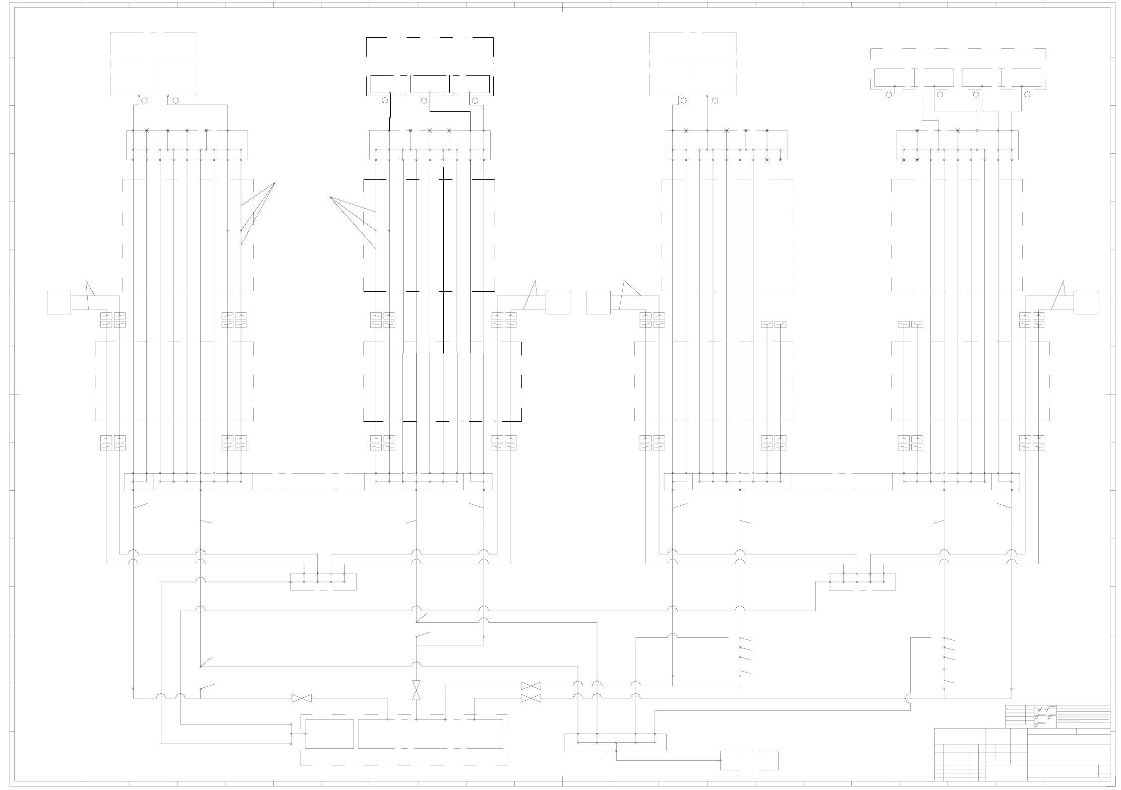
6 - 6
03038058-010101XD0 Pneumatic unit, SIPLACE HF series,
IGUS connecting diagram (Sh. 3 of 3)
Showing the compressed air connection
Showing the vacuum connection
Showing the vacuum connection
Showing the compressed air connection
3
C&P20 head
Holding circuit
1
2
Holding circuit
2.5 - 4.5 bar, 120 to 200 st.l/min
Return motion cyl.
Placement circuit
Placement circuit + return motion cylinder
4.5 ± 0.1 bar, 50 st.l/min.
Gantry distributor
SIPLACE X series
03034840-xx
Gantry distributor
SIPLACE X series
03034840-xx
Ø 10Ø 10Ø 6Ø 6Ø 6Ø 6Ø 6Ø 6
Ø 10 Ø 16
Ø 6 Ø 10Ø 10Ø 6Ø 6Ø 6Ø 6Ø 6Ø 6
Ø 10Ø 16
Ø 6 Ø 10Ø 10Ø 6Ø 6Ø 6Ø 6Ø 6Ø 6
Ø 10 Ø 16
Ø 6 Ø 10 Ø 10 Ø 6 Ø 6 Ø 6 Ø 6 Ø 6 Ø 6
Ø 10Ø 16
Ø 6
R
P
O
N
M
L
A
B
C
D
E
F
G
H
I
K
R
P
O
N
M
L
2120191817161 23456789101112131415
222120191817161 23456789101112131415
A
B
C
D
E
F
G
H
I
K
22
>400...1000
<6
>6...30
>30...120
>120...400
±0.1
±0.2
±0.3
±0.5
z
R 100
z
R 6.3
z
R 1
2-5 um layer (nickel-plated)
case hardened
HRc tempered
Surface.:
()
Dime ns. varia tions
±0.8
z
R 25
ECR no.
Drawing no. (FS RS DS DT L F)
Pneumatic unit, Siplace HF series
03038058-010101XD0
Degree of accuracy
General tolerances
for nominal dimensions as per
ISO 2768 mH, unless
otherwise specified
Siemens AG
Modification / ECO no. NameDate
DIN 7167
Stand.
Check.
Author
IGUS connecting diagram
A&D
Repl. f.
Schönbach07.03.05
NameDate
Scale
Material
3
3
She et
Sh.
Format
A0A0
Copying of this document, and giving it to others and the use
or communication of the contents thereof, are forbidden with-
out express authority. Offenders are liable to the payment of
damages. All rights are reserved in the event of the grant of
a patent or the registration of a utility model or design.
Weitergabe sowie Vervielfältigung dieser Unterlage, Verwer-
tung und Mitteilung ihres Inhalts nicht gestattet, soweit nicht
ausdrücklich zugestanden. Zuwiderhandlungen verpflichten zu
Schadenersatz. Alle Rechte für den Fall der Patenterteilung
oder GM-Eintragung vorbehalten.
03038773-xx)
03038773-xx)
03038773-xx)
Gantry 4Gantry 3Gantry 2Gantry 1
PVC hose with woven fabric inlay, Ø 16x4
PVC hose with woven fabric inlay, Ø 16x4
Fan unit
(Elmo)
03006294-xx
Pneumatic unit, Siplace X series
03038058-xx
Valve block, SIPLACE X series
03038355-xx
1
2
TwinHead / Pick&Place head
03001841-xx
Return motion cyl.
Z axis
Vacuum generator
1
2
4.5 ± 0.1 bar, 100 st.l/min.
Vacuum generator
Return motion cyl.
Z axis
PUN-CM-6-7X-SA (4.6m)
03038005-xx
PUN-CM-6-7X-SA (4.6m)
03038005-xx
PUN-CM-6-7X-SA (4.6m)
03038005-xx
PUN-CM-6-7X-SA (4.6m)
03038005-xx
Camozzi PUR C98A 10x1 (0.45m)
03021925-xx
Camozzi PUR C98A 10x1 (0.35m)
03021925-xx
Camozzi PUR C98A 10x1 (0.45m)
03021925-xx
Camozzi PUR C98A 10x1 (0.35m)
03021925-xx
Camozzi PUR C98A 10x1
03021925-xx
Camozzi PUR C98A 10x1
03021925-xx
Camozzi PUR C98A 10x1
03021925-xx
Camozzi PUR C98A 10x1
03021925-xx
Camozzi PUR C98A 10x1
03021925-xx
Camozzi PUR C98A 10x1
03021925-xx
Camozzi PUR C98A 10x1
03021925-xx
Camozzi PUR C98A 10x1
03021925-xx
Camozzi PUR C98A 10x1
03021925-xx
Camozzi PUR C98A 10x1
03021925-xx
Camozzi PUR C98A 10x1
03021925-xx
Camozzi PUR C98A 10x1
03021925-xx
TS 1612, SMC (2.0m)
03004163-xx
TS 1612, SMC (2.0m)
03004163-xx
QS-16
03035036-xx
QSC 12H, Festo
03015210-xx
QS-16
03035036-xx
QS-16
03035036-xx
QSH-16-12
03035037-xx
QS-12
03035034-xx
QS-16
03035036-xx
QSH-16-12
03035037-xx
QS-12
03035034-xx
PUN 12 x 2.0 (0.1m)
00344918-xx
PUN 12 x 2.0 (0.1m)
00344918-xx
PUN 10 x 1.5 (2.1m)
00324466-xx
PUN 10 x 1.5 (2.1m)
00324466-xx
PUN 10 x 1.5 (3.0m)
00324466-xx
TS 1612, SMC (2.8m)
03004163-xx
PUN 10 x 1.5 (3.0m)
00324466-xx
TS 1612, SMC (2.8m)
03004163-xx
Vacuum retrofit kit 1G and 2G O
03038195-xx
or
Vacuum retrofit kit 2G E
03039015-xx
QSC 12H, Festo
03015210-xx
Nozzle Ø 1.5mm
Suct. pwr.:63N/l
Air consmpt.:140Nl/min
Nozzle Ø 1mm
Suct. pwr.:27N/l
Air consmpt.:55Nl/min
Forced air
Plcmt. circuit
Holding circuit
1
2
C&P head DLM2-6, 00367020-xx
C&P head DLM2-12, 00367281-xx
4.5 +0.1 bar, 200 st.l/min.
Air consmpt.:5Nl/min
Nozzle Ø 1.5mm
Suct. pwr.:63N/l
Air consmpt.:140Nl/min
Nozzle Ø 1mm
Suct. pwr.:27N/l
Air consmpt.:55Nl/min
Forced air
Plcmt. circuit
Holding circuit
1
2
C&P head DLM2-6, 00367020-xx
C&P head DLM2-12, 00367281-xx
4.5 +0.1 bar, 200 st.l/min.
Air consmpt.:5Nl/min
Ø 8
Ø 8
Ø 6
Ø 6
Ø 6
Ø 6
Ø 6
Ø 6
Ø 12
Cable and hose carrier
(Y carrier, IGUS chain)
Cable and hose carrier
(X carrier)
Ø 6 Ø 4 Ø 4 Ø 6 Ø 8
Ø 6
Distributor, placement head vacuum
03029190-xx
Ø 8
Ø 8
Ø 6
Ø 6
Ø 6
Ø 6
Ø 6
Ø 6
Ø 12
Cable and hose carrier
(Y carrier, IGUS chain)
Cable and hose carrier
(X carrier)
Ø 6Ø 4Ø 4Ø 6Ø 8
Ø 6
Ø 8
Ø 8
Ø 6
Ø 6
Ø 6
Ø 6
Ø 6
Ø 6
Ø 12
Cable and hose carrier
(Y carrier, IGUS chain)
Cable and hose carrier
(X carrier)
Ø 6 Ø 4 Ø 4 Ø 6 Ø 8
Ø 6
Ø 8
Ø 8
Ø 6
Ø 6
Ø 6
Ø 6
Ø 6
Ø 6
Ø 12
Cable and hose carrier
(Y carrier, IGUS chain)
Cable and hose carrier
(X carrier)
Ø 6Ø 4Ø 4Ø 6Ø 8
Ø 6
Distributor, placement head vacuum
03029190-xx
Distributor, placement head vacuum
03029190-xx
Distributor, placement head vacuum
03029190-xx
Vacuum pump
Cooling air distributor, X series
03022295-xx
Ø 10Ø 10Ø 10Ø 10
Cooling air distributor, X series
03022295-xx
Ø 10Ø 10Ø 10Ø 10
TS 1612, SMC
(from the basic module vacuum supply
03038773-xx)
X X
Ø 16Ø 16Ø 16
Øxx
Ø 16
Vacuum distributor, SIPLACE X series
03034629-xx
TS 1612, SMC
(from the basic module vacuum supply
TS 1612, SMC
(from the basic module vacuum supply
TS 1612, SMC
(from the basic module vacuum supply
Y motor
Y motor
Y motor
Y motor