HF Circuit .pdf - 第282页
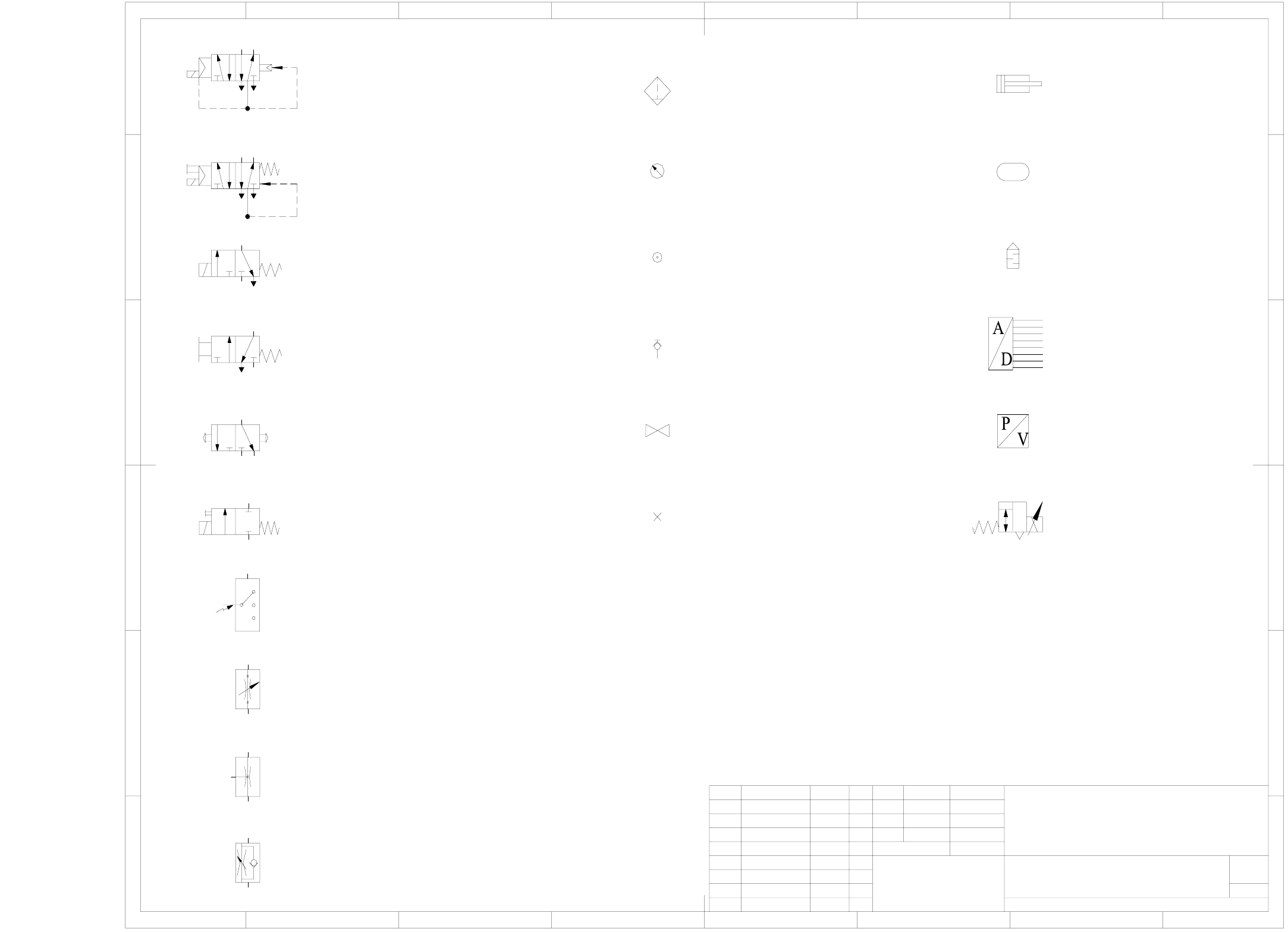
6 - 7 0032990 6-010 101EX 3 Pneuma tic symbo ls 1 5/2-way solenoid valve w ithout manu al override 8 Sheet Sh. 1 234 7 6 5 F E D C A B F E D C A B 1 234 8 7 6 5 A&D EA SI EMENS FS ES US UA S F 1 00329906 - 0101 01EX …
6 - 6
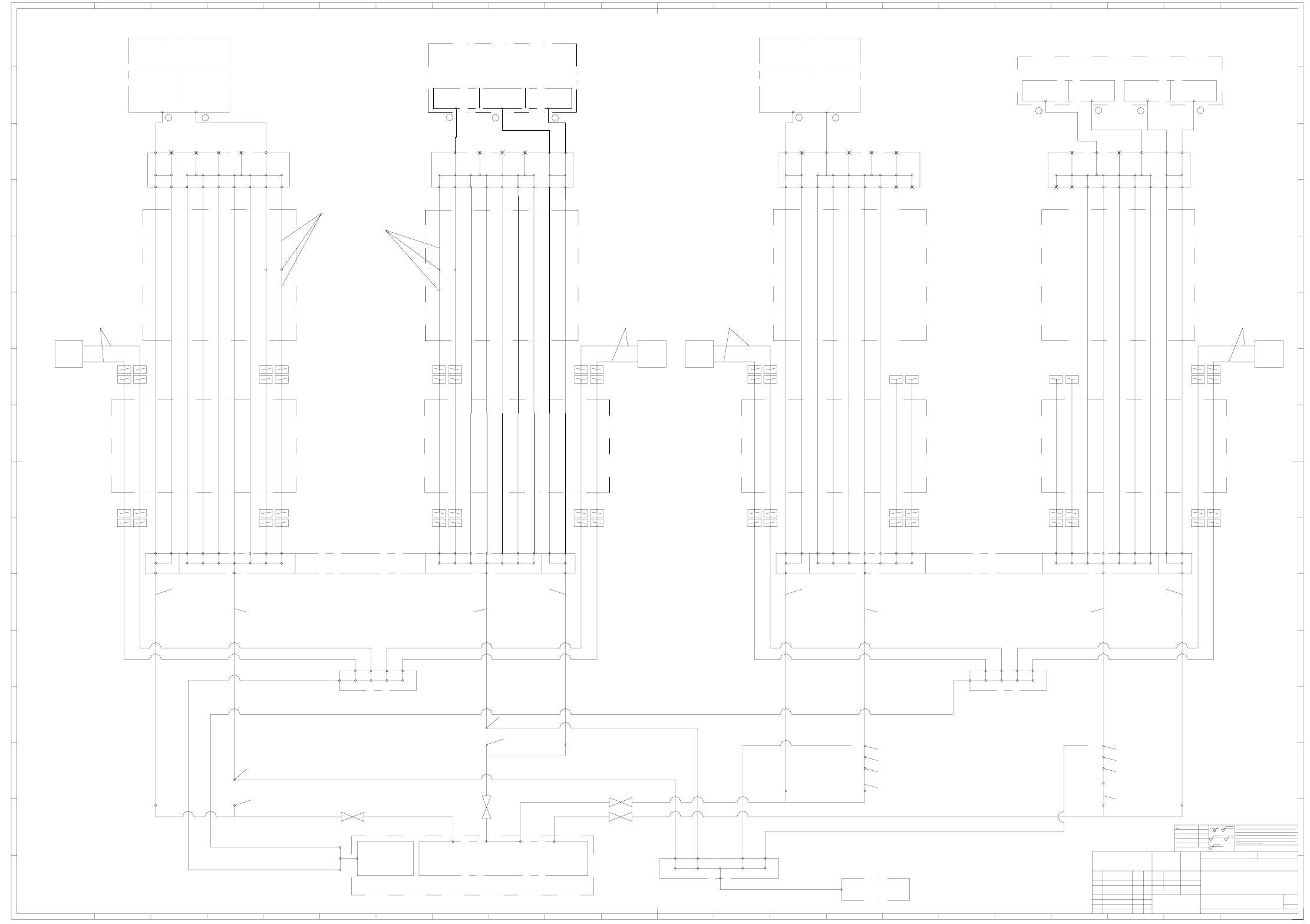
03038058-010101XD0 Pneumatic unit, SIPLACE HF series,
IGUS connecting diagram (Sh. 3 of 3)
Showing the compressed air connection
Showing the vacuum connection
Showing the vacuum connection
Showing the compressed air connection
3
C&P20 head
Holding circuit
1
2
Holding circuit
2.5 - 4.5 bar, 120 to 200 st.l/min
Return motion cyl.
Placement circuit
Placement circuit + return motion cylinder
4.5 ± 0.1 bar, 50 st.l/min.
Gantry distributor
SIPLACE X series
03034840-xx
Gantry distributor
SIPLACE X series
03034840-xx
Ø 10Ø 10Ø 6Ø 6Ø 6Ø 6Ø 6Ø 6
Ø 10 Ø 16
Ø 6 Ø 10Ø 10Ø 6Ø 6Ø 6Ø 6Ø 6Ø 6
Ø 10Ø 16
Ø 6 Ø 10Ø 10Ø 6Ø 6Ø 6Ø 6Ø 6Ø 6
Ø 10 Ø 16
Ø 6 Ø 10 Ø 10 Ø 6 Ø 6 Ø 6 Ø 6 Ø 6 Ø 6
Ø 10Ø 16
Ø 6
R
P
O
N
M
L
A
B
C
D
E
F
G
H
I
K
R
P
O
N
M
L
2120191817161 23456789101112131415
222120191817161 23456789101112131415
A
B
C
D
E
F
G
H
I
K
22
>400...1000
<6
>6...30
>30...120
>120...400
±0.1
±0.2
±0.3
±0.5
z
R 100
z
R 6.3
z
R 1
2-5 um layer (nickel-plated)
case hardened
HRc tempered
Surface.:
()
Dime ns. varia tions
±0.8
z
R 25
ECR no.
Drawing no. (FS RS DS DT L F)
Pneumatic unit, Siplace HF series
03038058-010101XD0
Degree of accuracy
General tolerances
for nominal dimensions as per
ISO 2768 mH, unless
otherwise specified
Siemens AG
Modification / ECO no. NameDate
DIN 7167
Stand.
Check.
Author
IGUS connecting diagram
A&D
Repl. f.
Schönbach07.03.05
NameDate
Scale
Material
3
3
She et
Sh.
Format
A0A0
Copying of this document, and giving it to others and the use
or communication of the contents thereof, are forbidden with-
out express authority. Offenders are liable to the payment of
damages. All rights are reserved in the event of the grant of
a patent or the registration of a utility model or design.
Weitergabe sowie Vervielfältigung dieser Unterlage, Verwer-
tung und Mitteilung ihres Inhalts nicht gestattet, soweit nicht
ausdrücklich zugestanden. Zuwiderhandlungen verpflichten zu
Schadenersatz. Alle Rechte für den Fall der Patenterteilung
oder GM-Eintragung vorbehalten.
03038773-xx)
03038773-xx)
03038773-xx)
Gantry 4Gantry 3Gantry 2Gantry 1
PVC hose with woven fabric inlay, Ø 16x4
PVC hose with woven fabric inlay, Ø 16x4
Fan unit
(Elmo)
03006294-xx
Pneumatic unit, Siplace X series
03038058-xx
Valve block, SIPLACE X series
03038355-xx
1
2
TwinHead / Pick&Place head
03001841-xx
Return motion cyl.
Z axis
Vacuum generator
1
2
4.5 ± 0.1 bar, 100 st.l/min.
Vacuum generator
Return motion cyl.
Z axis
PUN-CM-6-7X-SA (4.6m)
03038005-xx
PUN-CM-6-7X-SA (4.6m)
03038005-xx
PUN-CM-6-7X-SA (4.6m)
03038005-xx
PUN-CM-6-7X-SA (4.6m)
03038005-xx
Camozzi PUR C98A 10x1 (0.45m)
03021925-xx
Camozzi PUR C98A 10x1 (0.35m)
03021925-xx
Camozzi PUR C98A 10x1 (0.45m)
03021925-xx
Camozzi PUR C98A 10x1 (0.35m)
03021925-xx
Camozzi PUR C98A 10x1
03021925-xx
Camozzi PUR C98A 10x1
03021925-xx
Camozzi PUR C98A 10x1
03021925-xx
Camozzi PUR C98A 10x1
03021925-xx
Camozzi PUR C98A 10x1
03021925-xx
Camozzi PUR C98A 10x1
03021925-xx
Camozzi PUR C98A 10x1
03021925-xx
Camozzi PUR C98A 10x1
03021925-xx
Camozzi PUR C98A 10x1
03021925-xx
Camozzi PUR C98A 10x1
03021925-xx
Camozzi PUR C98A 10x1
03021925-xx
Camozzi PUR C98A 10x1
03021925-xx
TS 1612, SMC (2.0m)
03004163-xx
TS 1612, SMC (2.0m)
03004163-xx
QS-16
03035036-xx
QSC 12H, Festo
03015210-xx
QS-16
03035036-xx
QS-16
03035036-xx
QSH-16-12
03035037-xx
QS-12
03035034-xx
QS-16
03035036-xx
QSH-16-12
03035037-xx
QS-12
03035034-xx
PUN 12 x 2.0 (0.1m)
00344918-xx
PUN 12 x 2.0 (0.1m)
00344918-xx
PUN 10 x 1.5 (2.1m)
00324466-xx
PUN 10 x 1.5 (2.1m)
00324466-xx
PUN 10 x 1.5 (3.0m)
00324466-xx
TS 1612, SMC (2.8m)
03004163-xx
PUN 10 x 1.5 (3.0m)
00324466-xx
TS 1612, SMC (2.8m)
03004163-xx
Vacuum retrofit kit 1G and 2G O
03038195-xx
or
Vacuum retrofit kit 2G E
03039015-xx
QSC 12H, Festo
03015210-xx
Nozzle Ø 1.5mm
Suct. pwr.:63N/l
Air consmpt.:140Nl/min
Nozzle Ø 1mm
Suct. pwr.:27N/l
Air consmpt.:55Nl/min
Forced air
Plcmt. circuit
Holding circuit
1
2
C&P head DLM2-6, 00367020-xx
C&P head DLM2-12, 00367281-xx
4.5 +0.1 bar, 200 st.l/min.
Air consmpt.:5Nl/min
Nozzle Ø 1.5mm
Suct. pwr.:63N/l
Air consmpt.:140Nl/min
Nozzle Ø 1mm
Suct. pwr.:27N/l
Air consmpt.:55Nl/min
Forced air
Plcmt. circuit
Holding circuit
1
2
C&P head DLM2-6, 00367020-xx
C&P head DLM2-12, 00367281-xx
4.5 +0.1 bar, 200 st.l/min.
Air consmpt.:5Nl/min
Ø 8
Ø 8
Ø 6
Ø 6
Ø 6
Ø 6
Ø 6
Ø 6
Ø 12
Cable and hose carrier
(Y carrier, IGUS chain)
Cable and hose carrier
(X carrier)
Ø 6 Ø 4 Ø 4 Ø 6 Ø 8
Ø 6
Distributor, placement head vacuum
03029190-xx
Ø 8
Ø 8
Ø 6
Ø 6
Ø 6
Ø 6
Ø 6
Ø 6
Ø 12
Cable and hose carrier
(Y carrier, IGUS chain)
Cable and hose carrier
(X carrier)
Ø 6Ø 4Ø 4Ø 6Ø 8
Ø 6
Ø 8
Ø 8
Ø 6
Ø 6
Ø 6
Ø 6
Ø 6
Ø 6
Ø 12
Cable and hose carrier
(Y carrier, IGUS chain)
Cable and hose carrier
(X carrier)
Ø 6 Ø 4 Ø 4 Ø 6 Ø 8
Ø 6
Ø 8
Ø 8
Ø 6
Ø 6
Ø 6
Ø 6
Ø 6
Ø 6
Ø 12
Cable and hose carrier
(Y carrier, IGUS chain)
Cable and hose carrier
(X carrier)
Ø 6Ø 4Ø 4Ø 6Ø 8
Ø 6
Distributor, placement head vacuum
03029190-xx
Distributor, placement head vacuum
03029190-xx
Distributor, placement head vacuum
03029190-xx
Vacuum pump
Cooling air distributor, X series
03022295-xx
Ø 10Ø 10Ø 10Ø 10
Cooling air distributor, X series
03022295-xx
Ø 10Ø 10Ø 10Ø 10
TS 1612, SMC
(from the basic module vacuum supply
03038773-xx)
X X
Ø 16Ø 16Ø 16
Øxx
Ø 16
Vacuum distributor, SIPLACE X series
03034629-xx
TS 1612, SMC
(from the basic module vacuum supply
TS 1612, SMC
(from the basic module vacuum supply
TS 1612, SMC
(from the basic module vacuum supply
Y motor
Y motor
Y motor
Y motor
6 - 7
00329906-010101EX3 Pneumatic symbols
1
5/2-way solenoid valve without manual override
8
Sheet
Sh.
1234 765
F
E
D
C
A
B
F
E
D
C
A
B
1234 8765
A&D EA
SIEMENS
FS ES US UA S F
1
00329906-010101EX3
Pneumatic symbols
01.07.2001
Hi
Hi
01.07.01
Name
Status
Date
DS 01
new
Modified
Name
Date
Stand.
Author
Check.
Main no.
(Drawing number)
with pneumatic spring return
with mechanical spring return
5/2-way solenoid valve with manual override
3/2-way solenoid valve without manual override
with mechanical spring return
2/2-way solenoid valve with manual override
with mechanical spring return
3/2-way valve, manually operated
by push-button
3/2-way valve, manually operated
Electrical switch
with mechanical spring return
Flow control valve, adjustable
Flow control valve
Flow control valve with flow adjustable in one direction
Quick acting coupling uncoupled,
Pressure source
Filter with water separator
Pressure gauge
closed by non-return valve
Shut-off valve
Plug Regulator with exhaust
Pressure / voltage converter
Analog / digital converter
Silencer
Air reservoir
Double acting cylinder
with manual draining
53
24
1
1
53
42
A
RP
ab
A2
R3 P1
b
a
SIPLACE HF Series Detailed Circuit Diagrams Folder
09/2005 US Edition
7 - i
7Options
00119470-010101LD3 Overview, ceramic substrate centering, dual conveyor 7 - 1
00119471-010101LD3 Overview, ceramic substrate centering, single conveyor 7 - 2
00119671-010501XD3 Ceramic substrate centering, HF series 7 - 3
00371907-010201LD3 Wiring, stopper, Long board option, placement area 1 7 - 4
00371909-010201LD3 Wiring, stopper, Long board option, placement area 2 7 - 5
03012668-010101LD3 PCB barcode wiring 7 - 6
00372356-010101LD3 Distributor, PCB barcode scanner 7 - 7