HF Circuit .pdf - 第52页
2 - 2 NH-050 101LD3 Emerg. -stop lo op, EME RG .-S TOP butto n, ST ART/ STOP button, protect ive swit ches (Sh. 2 of 5 ) 2 7 9 8 6 5 4 3 1 12 11 10 X133 7 9 8 6 5 4 3 1 2 X53 6 5 4 3 1 2 6 5 4 3 2 X52 1 n.u. n.u. n.u . 6…
2 - 1
2 Detailed circuit diagrams
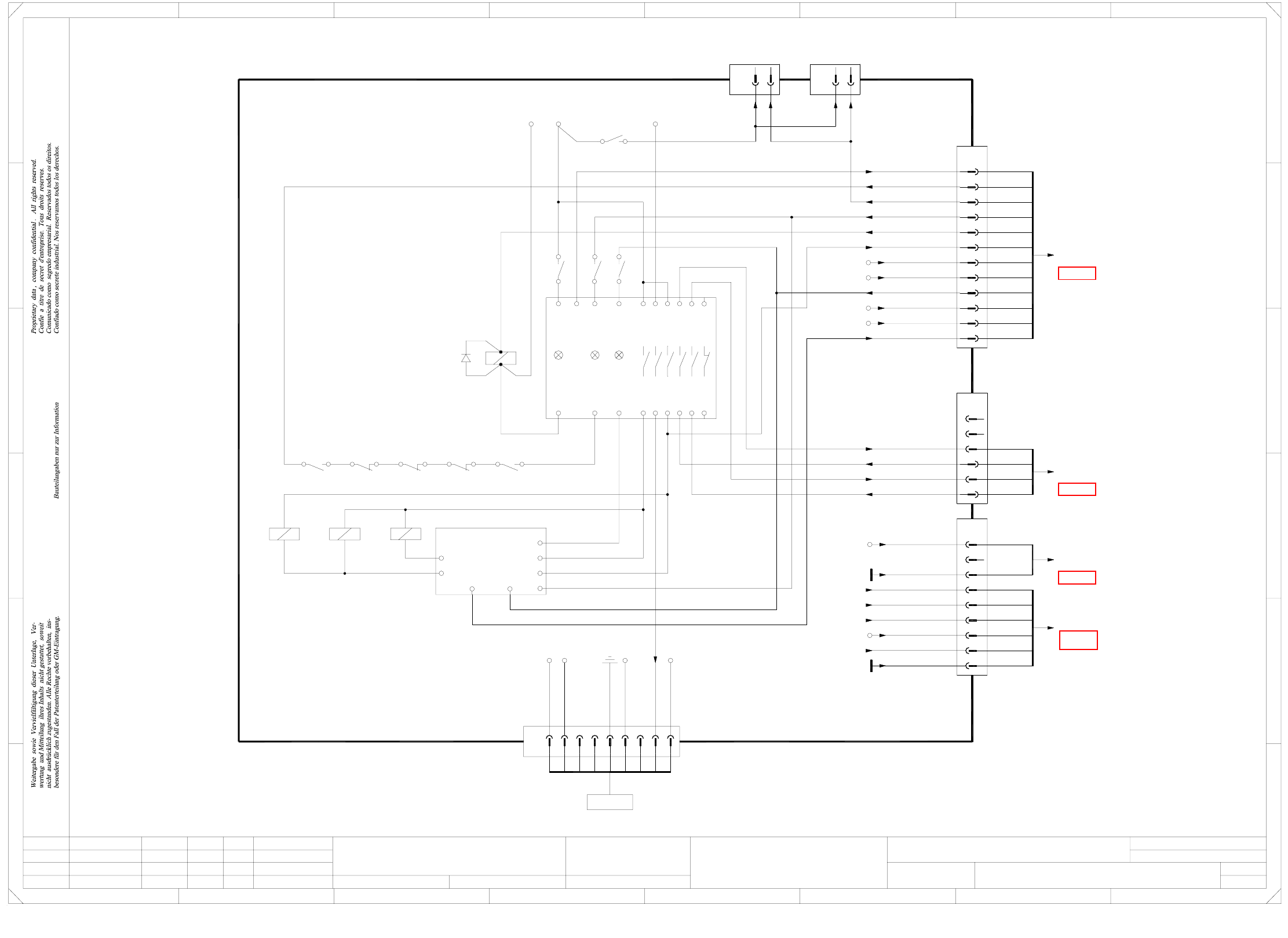
NH-050101LD3 Emerg.-stop loop, EMERG.-STOP button,
START/STOP button, protective switches (Sh. 1 of 5)
A2 (-) A1 (+)
V51
K5
K6
Inrush current
K2 K3
X7-11
ILS
X7-10
K4
limiter,
servo
X7-13
X8-19
X7-12
K1.4
4
3 2
K2.4
1 2
K3.4
1 2
K4.4
1 6
K5
5
X8-23 X8-20
03002506-xx
(Cable)
03002506-xx
(Cable)
03002505-xx
(Cable)
To plug X2qa
main distributor
(sheet 2)
(sheet 2)
main distributor
To plug X3qa
To plug X3qa
main distributor
(sheet 2)
n.u.
n.u.
S_EmergencyStopLoopOK
Voltage tape cutter
X20_6
X20_3
X20_6
X20_5
GND (+24V)
+24V
GND (+5V)
C_SoftwareON
Emergency-stop loop
S_GantryCrash
StartButton_ON
S_Ready
A2(-) A1(+)
A2(-) A1(+)
A1(+)A2(-)
S_TapeCutter
S_XY
GND(X6)
24
K5
13
K5
S_EmergencyStopLoopOK
Power supply unit
00354626-xx
X13
10
12
X14
12
To axis unit 1 To axis unit 2
4
K4.5
3
Servo Enable
P34V
Voltage PCB(+)
P24V
X20:3
GND(24)
X20:4
CSC43
CSC44
CSC53
CSC54
EmergencyStopLoop 2
EmergencyStopLoop 2
X8-21
EmergencyStopLoop
10
Contactor relay blocks
C
D
E
678
76
5.
1.
1.
22.09.05
22.09.05
22.09.05
17.12.2002
Hi
Emergency-stop loop
NH-050101LD3
1
5
Hi
Hi
Hi
Function status
Product status
Doc. status
SIPLACE HF series
Sheet
Sh.
NH-050101_SH01.DWG
Orig. Repl. f. Replaced by
Date
Author
Check.
Stand.NameDateModifiedStatus
Power supply
CAD file:
Mat. no.:
A&D EA
9
12
10
11
8
7
6
5
ye
gy
gn
bn
X16
2
3
4
1
bn
gn
wh
wh
(W4)
(W2)
(W2)
(W4)
(W1)
(W1)
(W3)
(W3)
(W3)
(W4)
(W4)
(W4)
1
2
1
2
X17
3
6
4
5
2
1
9
8
3
=
+
2
F
3
F
8
A
2
D
3
C
B
A
5
B
41
E
5
41
7
6
4
5
2
1
X18
2
1
(W2)
(W2)
(W3)1
2(W3)
(W4)1
n.u.
(W4)2
(W5)2
(W5)1
Vin(+)Illumination
F12
Vin(+)Illumination
F12
Vin(-)
Vin(-)
9
8
Voltage PCB(+)
X15
3
7
6
4
5
2
1
n.u.
n.u.
n.u.
Voltage PCB_Mot(+)
F8
U5(-)
Voltage PCB(-)
X20_4O
X20_3O
GND(+24V2)
+24V2
X79
To PCB conveyor
03002504-xx
(Cable)
supply
L+
L-
Power
CSC
24X4 X6 14 4434 54 66
23X1 X3 X5 13
Channel1 Channel2
6533 43 53
s
K5
8
7
+5V
GND (+24V)
+5V
GND (+5V)
+24V
X16:7
X16:8
X16:10
X16:11
1
2
3
4
(W6)
(W6)
(W6)
sub-distributor
To plug X3ra
(sheet 4)
(W6)
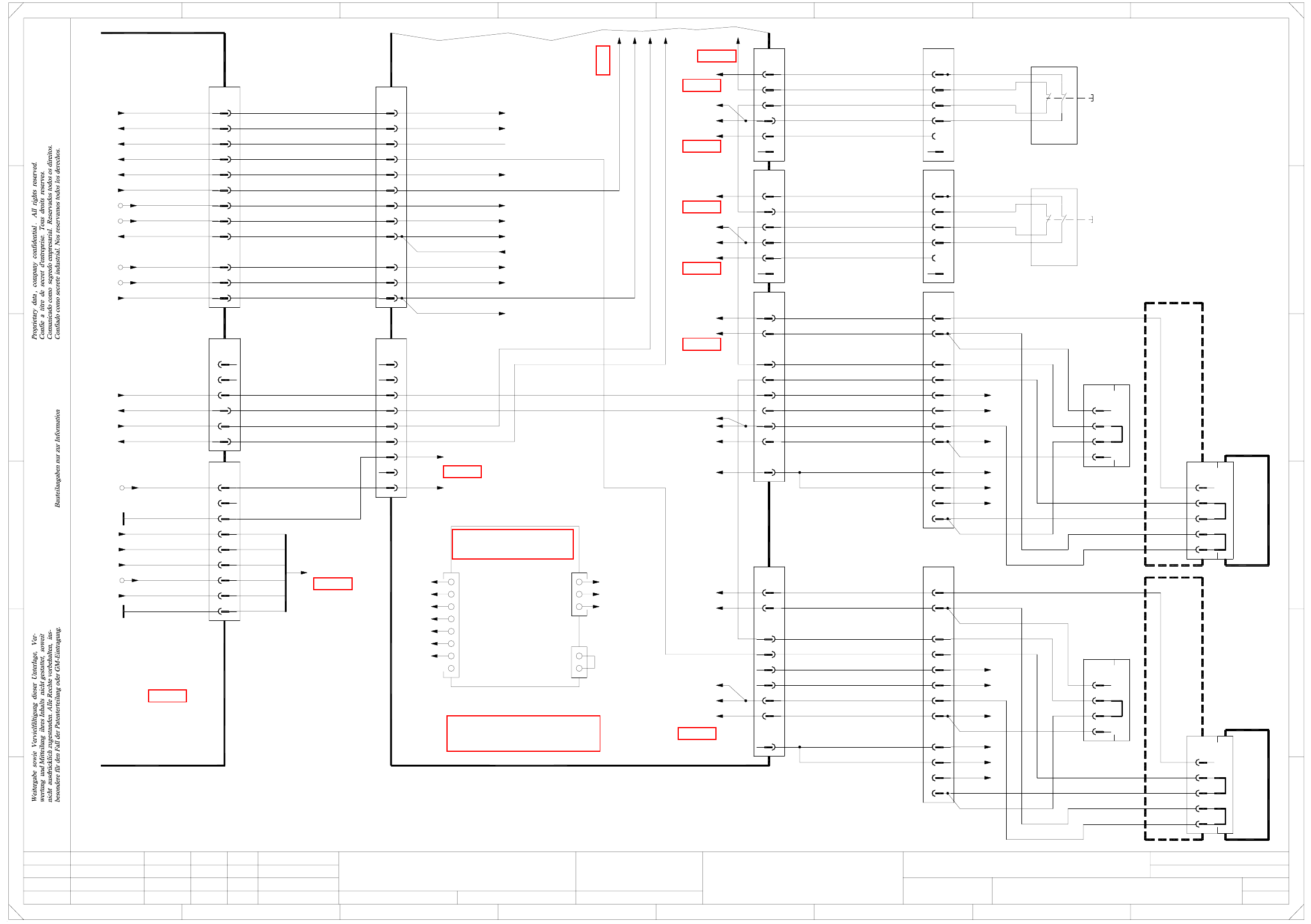
2 - 2
NH-050101LD3 Emerg.-stop loop, EMERG.-STOP button,
START/STOP button, protective switches (Sh. 2 of 5)
2
7
9
8
6
5
4
3
1
12
11
10
X133
7
9
8
6
5
4
3
1
2
X53
6
5
4
3
1
2
6
5
4
3
2
X52
1
n.u.
n.u.n.u.
6
X14qa
3
5
6
4
2
1
n.u.
X13qa
4
5
3
2
1
9
X18qa
4
8
7
6
5
2
3
1
9
4
8
7
6
5
2
3
X23qa
1
(Cable)
03002527-xx
GND
+24V
gr&pk
gn&ye
rd
bl
wh&bn
gn&ye
gr&pk
bl
wh&bn
bl
gr&pk
gn&ye
wh&bn
gn&ye
gr&pk
rd
bl
wh&bn
Emergency-stopLoop 1 in
Emergency-stopLoop 1 out
S_Hood2
Emergency-stopLoop 1 out
Emergency-stopLoop 1 in
S_Hood3
GND
(Cable)
+24V
03002528-xx
(Cable)
GND
03002531-xx
To plug X72qa_3
To plug X72qa_4
To plug X71qa_6
Main distributor
03010004 (qa)
21
22 12
11
03020409-xx
(Cable)
Location 2
Location 3
1121
1222
03020409-xx
(Cable)
(W2)wh
(W1)
(W1)1
2
(W1)
(W2)bn
4
5(W1)
(W1)6
(W1)
(W1)7
8
(W2)ye
(W1)
(W1)9
10
(W1)11
(W1)
(W2)gn
3
X12f
1
2
3
4
bk
Component trolley, docking unit
Location 2
Adapter connector
CO flap
03021042
X120
E29/30
B29/30
C29/30
D29/30
bk
rd
Location 2
Component trolley
(Cable)
03021020-W1/W2
11 (W1)
gn
3(W1)
(W2)
10
9
(W1)
(W1)
Location 3
Component trolley
E29/30
D29/30 rd
bkB28/30
C29/30
X130
5(W1)
ye
8
(W2)
(W1)
6
7
(W1)
(W1)
bn
4(W1)
(W2)
wh
2
(W2)
(W1)
X13f
4
3
2
1
bk
03021042
Adapter connector
CO flap
1(W1)
03021020-W1/W2
(Cable)
Location 3
Component trolley, docking unit
wh
gy
X1qa_Vin(+) illumination
9
12
10
11
8
7
6
5
ye
gy
gn
bn
X16
2
3
4
1
bn
gn
wh
wh
(W4)
(W2)
(W2)
(W4)
(W1)
(W1)
(W3)
(W3)
(W3)
(W4)
(W4)
(W4)
1
2
1
2
(Cable)
03002505-xx
X17
3
6
4
5
2
1
9
8
3
7
6
4
5
2
1
X18
2
1
(W2)
(W2)
(W3)1
2(W3)
(Cable)
03002506-xx
n.u.
n.u.
(W4)1
n.u.
(W4)2
(W5)2
(W5)1
Vin(+) illumination
F12
Vin(+) illumination
F12
Vin(-)
GND (+24V)
X20_6
X20_3
+24V
X20_5
X20_6
GND (+5V)
(Cable)
03002506-xx
Voltage tape cutter
S_Emergency-stopLoopOK
C_SoftwareON
Emergency-stopLoop
M_GantryCrash
StartButton_ON
S_Ready
(sheet 3)
Power supply
00354626-xx
(sheet 1)
(sheet 3)
(sheet 3)
(sheet 3)
(sheet 3)
(sheet 3)
(sheet 3)
(sheet 3)
(sheet 3)
(sheet 3)
(sheet 3)
(sheet 3)
CSC43
CSC54
CSC44
CSC53
CSC43
CSC44
CSC53
CSC54
Emergency-stopLoop 2
5. 22.09.05
s
A&D EA
NH-050101LD3
3
2
(W6)
(W6)
1(W6)
4
To plug X3ra
sub-distributor
(sheet 4)
+24V
GND (+5V)
+5V
GND (+24V)
X16:11
X16:10
X16:8
X16:7
(W6)
Emergency-stopLoop2End
X19qa_4
X1qe_2 (8x&)
X24qa_4
X1qe_6 (8x&)
X1qe_7 (8x&)
X5qb_7 (DI22)
03002535-xx
GND
(Cable)
+24V
+24V
Emergency-stopLoop 1 in
Emergency-stopLoop 1 out
Emergency-stopLoop 1 out
Emergency-stopLoop 1 in
gnye&1
gnye&1
2&3
4
5
6
7
8
9
10
11
n.u.
n.u.
2&3
4
5
6
7
8
9
10
11
n.u.
n.u.
S_Flap
S_Flap
S_Emerg.StopButtonMTC
S_COtable2
Emergency-stopLoopMTC2 in
Emergency-stopLoopMTC2 out
S_COtable3
X1qa_24V
X12qa_3
+24V
To plug
or
bk
X1qa_0V
GND
wh
bk
or
X1qa_24V
+24V
bk
X1qa_0V
GND
bk
wh
bk
wh
or
X1qa_0V
GND
X1qa_24V
+24V
bk
bk
X1qa_24V
X1qa_0V
+24V
GND
or
wh
bk
n.u.
n.u.
bk
bk
bk
bk
bk
Emergency-stopLoopMTC2 in
Emergency-stopLoopMTC2 out
X1qa_M_Flap
X1qa_S_Emerg.StopButtonMTC
Emergency-stopLoop
X1qa_34
X1qa_35
n.u.
X1qa_M_Flap
bk
bk
X1qa_34
n.u.
n.u.
n.u.
X1qa_0V
bk
bk
bk
bk
X4qb_2 (DI9)
bk
bk
bk
bk
pk
wh
bk
bk
wh
bk
bk
or
S_Ready
StartButton_ON
CAN I/O module
X1qa_StartButton
M_GantryCrash
n.u.
Emergency-stopLoop1End
C_SoftwareON
X1qa_SoftwareRelease
Voltage tape cutter
X5qb_1 (DI16)
X2qe_3 (8x&Output)
+5V
GND (+5V)
X1qa_0V
X1qa_5V
GND (+24V)
+24V
X1qa_24V
X1qa_0V
S_Emergency-stopLoopOK
X3qb_1 (DI0)
CAN I/O module
To plug X73qa_9
X5qb_3 (DI18)
X1qe_3 (8x&)
A29/30
A29/30
X1qe
X23qa_7
X14qa_4
X12qa_4
X72qa_5
X13qa_4
X11qa_4
X18qa_7
1
4
6
7
5
2
3
8
Emergency-stopLoop2
S_Hood2
S_COtable2
S_HoodPCBoutput
S_Emerg.StopButtonPCBoutput
S_Hood3
S_COtable3
n.u.
2
3
1
X2qe
2
1
X3qe
X1qa_0V
X1qa_24V
X2qa_9 output
PCB, 8-input AND gate
A5 (8x&)
bk
bk
bk
bk
bk
bk
Vin(-) illumination
Hood switch
Hood switch
=
+
2
F
3
F
8
A
2
D
3
C
B
A
5
B
41
E
5
41
C
D
E
678
76
1.
1.
22.09.05
22.09.05
17.12.2002
Hi
Emergency-stop loop
2
5
Hi
Hi
Hi
Function status
Product status
Doc. status
SIPLACE HF series
Sheet
Sh.
NH-050101LD3_SH02.DWG
Orig. Repl. f. Replaced by
Date
Author
Check.
Stand.NameDateModifiedStatus
Protective switch
Component trolley, docking unit
CAD file:
Mat. no.:
X123
12
11
10
9
8
7
2
4
6
5
3
1
X3qa
12
9
8
7
2
4
6
5
3
1
X2qa
10
11
See page 4-7
See page 5-52
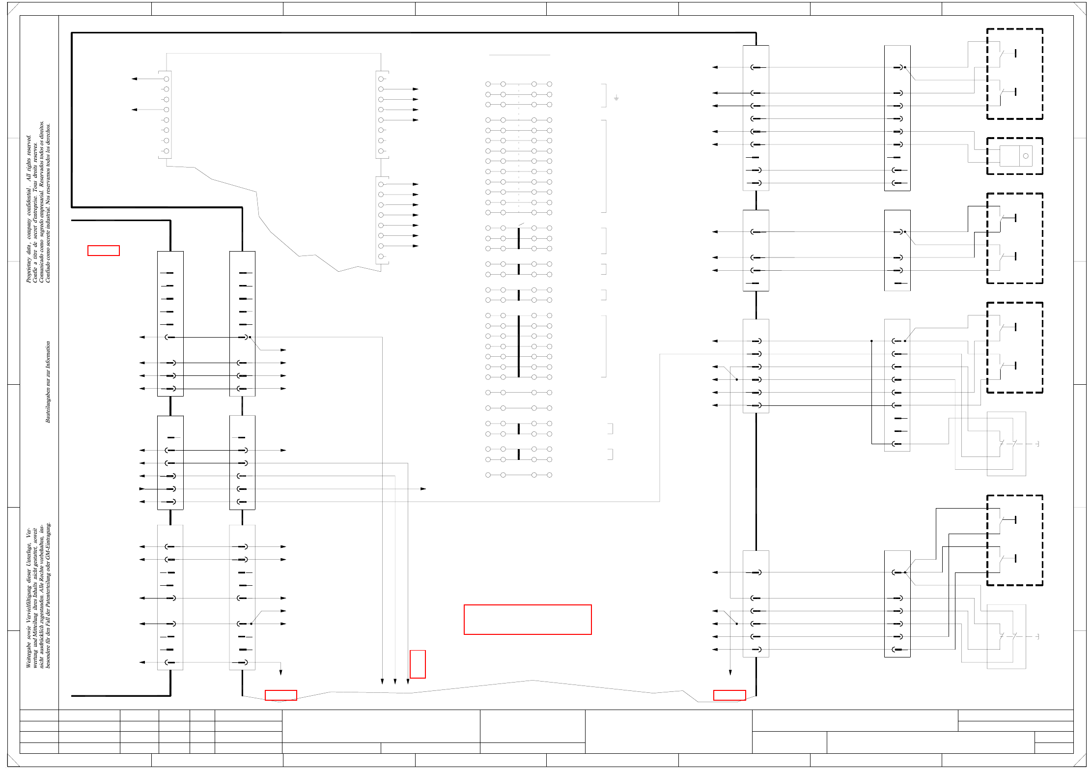
2 - 3
NH-050101LD3 Emerg.-stop loop, EMERG.-STOP button,
START/STOP button, protective switches (Sh. 3 of 5)
=
+
2
F
3
F
8
A
2
D
3
C
B
A
5
B
41
E
5
41
2
X63
12
11
22
21
(Cable)
03002525-xx
+24V
Emergency-stopLoop 1 in
Emergency-stopLoop 1 out
S_HoodPCBoutput
6
4
5
3
2
1
bk
bk
bk
bk
+24V
or
X11qa
2
6
5
4
3
X62
1
gn
vi
Emergency-stop
S3
4
3
4
3
Stop
S2
Start
S1
bk
X13qa_2
To plug
X1qa_24V
S_StartButton
S_StopButtonrd
X1qa_StartButton
X1qa_StopButton
bk rd
bl
ye&gy
br&gn
pk
wh
S_StopButton
S_StartButton
X1qa_StartButton
X1qa_StopButton
7
8
9
X1qa_24V
X10qa
4
3
2
1
X57
4
3
2
1
n.u.n.u.
wh&bn
gn
ye
+24V
03002524-xx
(Cable)
+24V
X1qa_24V
bn
S_StopButton
S_StartButton
X1qa_StopButton
X1qa_StartButton
6
4
5
bk
(Cable)
X73qa
1
2
bk
bk
03002521-xx
n.u.n.u.
bk
wh
bn
gy
pk
rd
X1qa_StopButton
X1qa_StartButton
X1qa_FlapX1ra_Flap
X1ra_StopButton
X1ra_StartButton
To plug
X2qa_12
To plug X3qa_6
To plug X3qa_5
To plug X2qa_6
03010004 (qa)
Main distributor
03010005 (ra)
Sub-distributor
(DC/DC converter)
X1qa_Vin(+)ill
28
X1qa_Flap
X1qa_StartButton
X1qa_StartButton
X1qa_StopButton
X1qa_StopButton
X1qa_SoftwareRelease
32
33
34
31
30
29
C
D
E
678
76
1.
1.
22.09.05
22.09.05
17.12.2002
Hi
Emergency-stop loop
3
5
Hi
Hi
Hi
Function status
Product status
Doc. status
SIPLACE HF series
Sheet
Sh.
NH-050101LD3_SH03.DWG
Orig. Repl. f. Replaced by
Date
Author
Check.
Stand.NameDateModifiedStatus
START buttons, STOP buttons
Protective switch
Emergency-stop push-button
CAD file:
Mat. no.:
03002526-xx
Emergency-stopLoop 1 out
Emergency-stopLoop 1 in
S_Emerg.StopButtonPCBoutput
+24V
(Cable)
3
5
6
4
2
1
bk
bk
or
+24V
bk
bk
bl
pk
br&gn
wh
ye&gy
X12qa
bk
rd
pk&bu
ye&gy
bn
wh
6
5
4
1
3
4
4
3
3
Stop
S2
Pneumatic panel
S1
Start
6
9
8
7
4
5
3
2
1
X56
+24V
03002523-xx
(Cable)
n.u.
n.u.
wh
pkbk
6
bn
gn
X1qa_24V
wh
or
bk
5
4
gy
ye
3
2
+24V
X9qa
1
n.u.
7
8
9
n.u.
n.u.
n.u.
n.u. n.u.
S_StopButton
S_StartButton
X1qa_StopButton
X1qa_StartButton
bk
bk
rd
bl
Control CO counter
GND
GND
X1qa_0V
X7qb_5(DO4)
4
3
4
3
S2
Stop
Start
S1
Power supply panel
bn
ye
gn
pk
gy
6
1
CO counter
3
4
X72ra
2
1
9
8
7
2
4
6
5
3
X71ra
1
03002519-xx
(Cable)
03002520-xx
(Cable)
3
4
2
1
X72qa
(W1)
(W1)
(W2)
(W1)
PCB output side, on the right
1121
22 12
PCB output side, on the right
Stop
4
4
3
3
S2
Start
S1
(Cable)
03020410-xx
Cover flap, PCB conveyor
bk
7
8
1
4
6
5
3
2
X11qa_4
X12qa_4
X18qa_7
D22
D23
D19
D21
D20
D18
D17
D16
X2qa_9
X19qa_4
X23qa_7
X24qa_4
bk
bk
bk
bk
bk
bk
S_COtable2
S_COtable3
S_HoodPCBoutput
S_Hood3
n.u.
Emergency-stopLoop2OK
S_Hood2
S_Emerg.StopButtonPCBoutput
DO7
DO6
DO5
DO4
DO3
DO2
DO1
DO0DI0
DI1
DI2
DI3
DI4
DI5
DI6
DI7
bk
bk
X5qb
Emergency-stopLoop1OK
bk
n.u. n.u.
n.u.n.u.
n.u.
n.u. n.u.
n.u.
n.u.n.u.
n.u.
bk
bk
bk
n.u.
n.u.
bk
ye
gn
bn
rd
or
bn
wh
(W1)
(W2)
(W2)
(W2)
X1qa_24V
X1qa_-15V
X1qa_-15V
X1qa_+15V
X1qa_+15V
X1qa_24V
X1qa_24V
X1qa_24V
X1qa_24V
X1qa_24V
X1qa_24V
X1qa_0V
7
18
23
26
24
25
27
20
21
22
19
13
14
15
16
17
8
9
10
11
12
X1qa_0V
Bridge
X1qa_5V
X1qa_5V
X1qa_5V
9
8
7
2
4
6
5
bk
3
1
X71qa
(W3)gn&ye
5
6
5
6
n.u.
(W3)
(W3)2
3
(W3)1
X1ra_0V
X17ra_4
X2rc_7 (V illuminationB)
X2rc_9 (V illuminationA)
gy
wh
gy
bk
Voltage tape cutter
X17qa_4
X1qa_0V
GND
X2qc_9 Voltage illuminationB
X2qc_7 Voltage illuminationA
X23ra_4
X1qa_Emerg.StopButtonMTC
bk
bk
bk
bk
X23ra_6
X23ra_5
X23ra_9
bn (W1)
gn (W1)
bn (W2)
wh (W2)
gn (W2)
Emergency-stopLoop1input
Emergency-stopLoopMTC4out (SSK54)
Emergency-stopLoopMTC4in (SSK53)
3
9
8
7
X18ra_7
6
4
5
1
2
X73ra
3
9
8
7
bk
X1qa_0V
X1qa_0V
X1qa_0V
X1qa_0V
X1qa_0V
Terminals overview
X1qa
2
6
5
3
4
1
ab
X1qa_PE
X1qa_0V
X1qa_0V
X1qa_0V
X1qa_PE
cd
X1qa_PE
+15V
24V
-15V
5V
GND
EARTHING
bk
bk
X1qa_Flap
A1
EmergencyStopLoopOK
CAN I/O module
X3qb
n.u.
3
n.u.
n.u.
n.u.
n.u.
6
7
8
S_Flap
4
5
n.u.
1
2
Ctrl_ComponentCounter
Ctrl_CompressedAirPressure C&P/TWIN
3
n.u.
6
n.u.
n.u.
7
8
4
5
SoftwareRelease
n.u.
X7qb
1
2
X1qa_SoftwareRelease
bk
PCB output side, on the left
(sheet 2)(sheet 2)
(sheet 2)
(sheet 4)
03020687-xx
(Cable)
5. 22.09.05
s
A&D EA
NH-050101LD3
X5qb_4 (DI19)
X1qe_4 (8x&)
X5qb_5 (DI20)
X1qe_5 (8x&)
03004702-xx
(Cable)
03004701-xx
(Cable)
Emergency-stopLoop2inputbk
X1qe_1 (8x&)
Emergency-stopLoop1OK
n.u.n.u.
n.u.
n.u.
n.u.
n.u.
S_ControlOn
X24qa_7
X4qa_6
X2re_3
n.u.
(8x& output)
X2qa_12
K1_A1
K2_A2
X9qa_5
See page 4-7