HF Circuit .pdf - 第80页
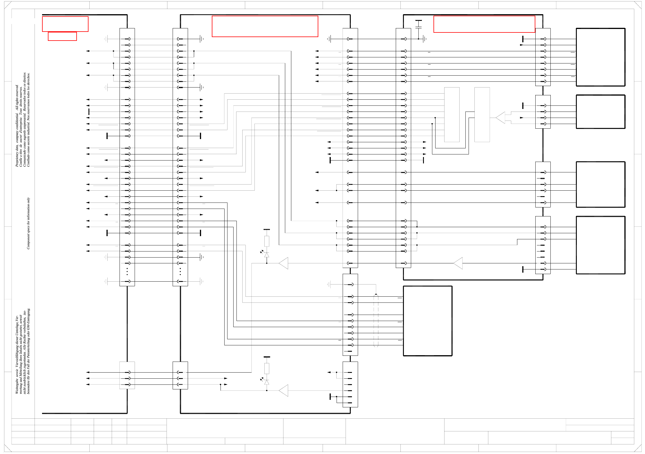
2 - 30 ZTH012-010101LD3 Z2 axis, T winHead, P&P module 2, gantry 1, HF (Sh. 2 of 4) 22 23 21 20 19 17 18 16 11 14 15 12 13 8 9 10 7 1 3 5 4 2 30 31 32 35 34 33 50 PE 03000902-xx (br) P&P he ad a dap ter Key Z2 mo…
2 - 29
ZTH012-010101LD3 Z2 axis, TwinHead, P&P module 2, gantry 1, HF (Sh. 1 of 4)
8
9
11
10
12
13
14
17
16
20
19
18
21
23
22
24
26
25
15
2
1
3
4
6
7
5
X8bd
30
28
29
27
8
15
25
26
24
22
23
21
18
19
20
16
17
14
13
12
10
11
9
5
7
6
4
3
X8be
1
2
03005289-xx
DP unit control cable
PE PE
DP2 track N
DP2 track N
DP2 track B
DP2 track B
DP2 track A
DP2 track A
GND
X30bd:32
C600 head main board, P&P module 2
00352833-xx (bd) 00352809-xx (be)
C700 TwinHead force meas. board, P&P module 2
Force sensor
X30bd:33
X30bd:30
X30bd:29
X30bd:26
X30bd:27
DP1 track N
DP1 track B
DP1 track B
DP1 track A
DP1 track N
DP1 track A
GND
Z1-Force-DATA
Z1-Force-DATA
Z1-Force-CS
Z1-Force-CS
Z1-Force-Dir
Z1-Force-Dir
Z1-Force-SCLK
Z1-Force-SCLK
-15V
+15V
+5V
-15V
+15V
+5V
DP2 motor U
DP2 motor V2
DP2 motor V1
DP2 motor W
Z2 motor V
Z2 motor U
Z2 motor W
Z2 temperature sensor
=
Date
Check.
Stand.
Author
Sheet
Orig. Repl. f. Repl. byNameDateModifiedStatus
Sh.
+
2
F
3
F
8
A
2
D
3
C
B
A
5
B
41
E
5
41
Z2 axis, TwinHead, P&P module 2
Function st.
C
D
E
678
76
1.
1.
1.
22.09.05
22.09.05
22.09.05
22.09.2005
Hi
ZTH012_HF-010101LD3
1
4
Hi
Hi
Hi
Product st.
Document st.
SIPLACE HF series
ZTH012_HF-010101LD3_SH01.DWG
CAD file :
Mat. no. :
27
29
28
30
32
35
34
33
50
+5V7
RI
2
3
4
X5bd
GND
1
8
GND
T1
T2
T2
T1
1
4
6
5
3
2
X4bd
Z2 axis
03000102-xx
Encoder
10
9
RI
6
5
bk
gy
bn
gn
wh
rd
pk
ye
whgn
Key
Key
+5V
PE
03000902-xx (br)
P&P head adapter
Key
Z2 motor U
Z2 motor V
Z2 motor W
PE
Gantry-ID-Bit 0
Gantry-ID-Bit 1
Gantry-ID-Bit 2
Power-Fail
Z2-Force-Dir
Z2-Force-Dir
GND
GND
VCC
-15V
+15V
Z2-Force-CS
Z2-Force-CS
Z2-Force-SCLK
Z2-Force-SCLK
Z2-Force-DATA
Z2-Force-DATA
PE
n.u.n.u.
PE
PE
GNDGND
+24V+24V
Z2 track N
Z2 track N
Z2 track B
Z2 track B
Z2 track A
Z2 track A
Z2 track N
Z2 track N
Z2 track B
Z2 track B
Z2 track A
Z2 track A
Z2 track N
Z2 track N
3
2
GND
U-Sensor+
-
1
28
30
29
25
26
27
24
6
22
23
21
19
20
16
18
17
11
14
15
13
12
8
10
9
7
1
3
5
4
2
X31bd
50
35
33
34
32
31
PE
PE
Key
PE
GND
Z2-Force-Dir
Z2-Force-Dir
Z2-Force-CS
Z2-Force-CS
Z2-Force-DATA
Z2-Force-DATA
Z2-Force-SCLK
Z2-Force-SCLK
+5V
-15V
+15V
Gantry-ID-Bit 0
Gantry-ID-Bit 1
Power-Fail
P&P-Head-ID-Bit
Z2 motor W
Z2 motor V
Z2 motor U
Twin flat ribbon cable loom
03004332-W4
X33br
28
29
25
27
26
24
6
22
23
21
20
19
17
18
16
11
14
15
12
13
8
9
10
7
1
3
5
4
2
30
31
X30bd:6, 7
X30bd:4, 5
X30bd:2, 3
Z1 motor V
Z1 motor U
Z1 motor W
Z2 temperature sensor
DP1 motor W
DP1 motor V
DP1 motor U
or D15
C37
220n
DP2 axis
7
8
1
3
2
4
6
5
T1
RSF encoder
+5V
GND
X18be
03000046-xx
+5V
GND
T2
T2
T1
RI
RI
2
1
3
4
X16be
6
5
DP2 axis
03001556-xx
DISC-Magnetic-Motor
A+ (U)
A- (V)
B+ (V)
B- (W)
Key
Key
gy
bu
bn
ye
8
5
7
6
4
3
X17be
GND
1
2
Key
Key
Key
ye
bn
00353135-xx
Linear motor
Z2 motor
gy
wh
bu
Temperature sensor
4
3
X15be
1
2
Force transducer
03000100-xx
OUT -
U-Sensor +
GND
OUT +
J13 J12
7
2
1
6
14
10
9
15
Z2 track B
Z2 track B
Z2 track A
Z2 track A
PE
d6green
X30bd
24
21 Z2 reference point
Z2 temperature sensor
X2bd:78
Z2 reference point
Sheet 2
03004332-W3
Twin flat ribbon cable loom
23
Z2 clamping
X32br
24
23
21
Z2 temperature sensor
Z2 clamping
Z2 reference point
Gantry 1
HF
A&D EA
s
See page 5-16
See page 5-15
See page 5-46
2 - 30
ZTH012-010101LD3 Z2 axis, TwinHead, P&P module 2, gantry 1, HF (Sh. 2 of 4)
22
23
21
20
19
17
18
16
11
14
15
12
13
8
9
10
7
1
3
5
4
2
30
31
32
35
34
33
50
PE
03000902-xx (br)
P&P head adapter
Key
Z2 motor U
Z2 motor V
Z2 motor W
PE
Gantry-ID-Bit 0
Gantry-ID-Bit 1
Gantry-ID-Bit 2
Power failure
Z2-Force-Dir
Z2-Force-Dir
GND
GND
VCC
-15V
+15V
Z2-Force-CS
Z2-Force-CS
Z2-Force-SCLK
Z2-Force-SCLK
Z2-Force-DATA
Z2-Force-DATA
n.u.
PE
PE
GND
+24V
Z2 track N
Z2 track N
Z2 track B
Z2 track B
Z2 track A
Z2 track A
From sheet 1
X32br
24
23
21
Z2 temperature sensor
Z2 clamping
Z2 reference point
83,85
28
22
24
7,13,134,140
135
1
133
=
Date
Check.
Stand.
Author
Sheet
Orig. Repl. f. Repl. byNameDateModifiedStatus
Sh.
+
2
F
3
F
8
A
2
D
3
C
B
A
5
B
41
E
5
41
C
D
Z2 axis, TwinHead, P&P module 2
Function st.
E
678
76
1.
1.
1.
22.09.05
22.09.05
22.09.05
22.09.2005
Hi
ZTH012_HF-010101LD3
2
4
Hi
Hi
Hi
Product st.
Document st.
SIPLACE HF series
ZTH012_HF-010101LD3_SH02.DWG
CAD file :
Mat. no. :
X33br
28
29
25
27
26
24
6
23
21
22
25
24
23
21
GND GND
Z1-Dir
+5V+5V
-15V-15V
+15V+15V
Z2-Force-CS
Z2-Force-CS
Z2-Force-SCLK
Z2-Force-SCLK
Z2-Force-DATA
Z2-Force-DATA
Z2 clamping
Z2 reference point
30
32
33
27
29
28
26
30
32
33
27
29
28
26
+24V +24V
15
15 Z2 temperature sensor
Z2 track A
Z2 track A
Z2 track B
Z2 track B
Z2 track N
Z2 track N
or
03010004-xx (qa)
X1qa_+24V
X1qa_+15V
Main distributor
X1qa_+5V
X1qa_0V
X1qa_-15V
wh
pk
bu
rd
X1qa
(W1)wh1
+24V
1
Cable carrier interface
03009788-xx W1/W2
(W1)
(W1)
(W2)
(W2)
14
6
5
KEY
2
3
2
gn
bn
4
5
3
2
+5V
GND
+15V
-15V
X6qa X50ba
23 23
24
25
26
26
24
25
1
3
4
2
6
5
8
9
11
12
10
7
15
14
16
13
18
17
19
21
20
22
Axis distributor I/O
00353487-xx A48 (to)
Sheet 4/D7
n.u.
Z2 track B
GND
Z2 track B
Z2 track N
Z2 track N
Z2 track A
Z2 track A
PE
11
17
20
21
22
18
19
14
15
16
n.u.
12
13
X5to
S/Z2 axis
Actual value
8
10
9
7
6
GND
4
5
3
X23ba
PE1
2
03009793-xx
Z2 track A
Z2 track A
Z2 track B
Z2 track B
Z2 track N
Z2 track N
03002163-W4
bn
bk
Sheet 3 / E7
00353484-xx A35 (tv)
Z2 axis / TwinHead
Servo ampl. backplane
Z2 motor W bn3
03016110-xx
Axis unit
Z2 motor V
Z2 motor U
X3tv
2
1
rd
bk
(Cable)
bnbn34
Z2 motor W3
45 bk bk 4 PE
rd 40 gn
X21
46 wh
gn
wh
03009782-xx
Cable carrier interface
Z2 motor V
Z2 motor U
2
1
X13ba
S/Z2 motor
Voltage
+5V +5V
Z2-Force-DATA
Z2-Force-DATA
Z2-Force-SCLK
Z2-Force-SCLK
Z2-Force-CS
Z2-Force-CS
Z2-Force-CS
Z2-Force-CS
Z2-Force-SCLK
Z2-Force-SCLK
Z2-Force-DATA
Z2-Force-DATA
Z2 temperature sensor
Z2 temperature sensor
Z2 reference point
Z2 reference point
Z2-Dir
Z2-Dir
Z2 clamping
Z2 clamping
Gantry 1
wh
HF
X5ba X5bc
1,11,14,34
PE1,11,14,34PE
03001725-xx
Carrier cable 5
X motor
3
6
5
4
2
A&D EA
s
107,109
108,110,112,114
X22bc/J3
111,113
91,92
PE
X14bc:73
X14bc:71
X13bc:73
2
3
1
U2
I1
U1
Z2-Dir
16
12
88,90
14
20
87,89
18
GND
PE
GND
VCC
-15V
+15V +15V
-15V
VCC
66
2
4
8
6
84,86
10
51
26
+24V
+24V
Gantry 3
C600 head interface
03000901-xx (bc)
X6bc
14
12
8
4,5
1,8,9,10,34
2
PE
X6ba
7
12
14
4
6
5
1,8,9,10,34
3
2
PE
03010612-xx (ba)
Cable carrier interface
Gantries 1 or 3
6,7
9
3
Z2 motor W
Z2 motor V
Z2 motor U
S/Z2 motor
Carrier cable 6
03001726-xx
16,31
15
16,31
15
18
20
19
17
18
20
19
17
22
25
24
See page 4-18
See page 5-57
See page 5-44
See page 5-46
See page 5-27
See page 4-7
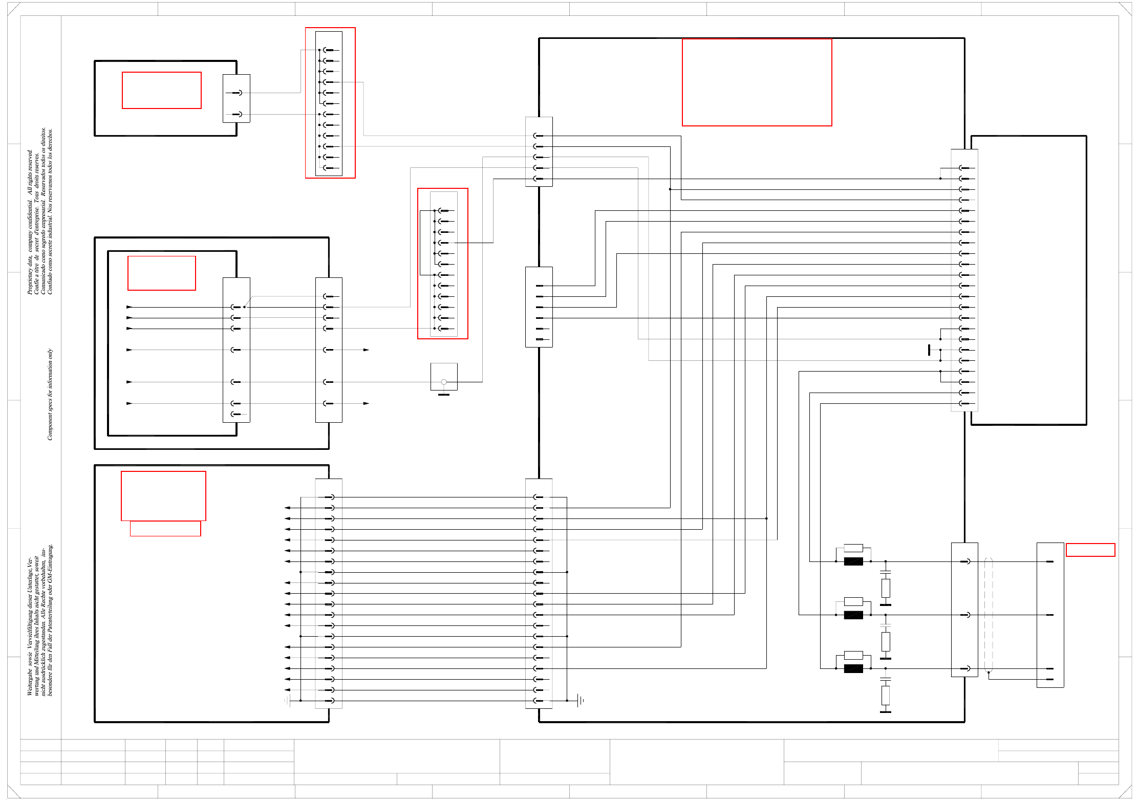
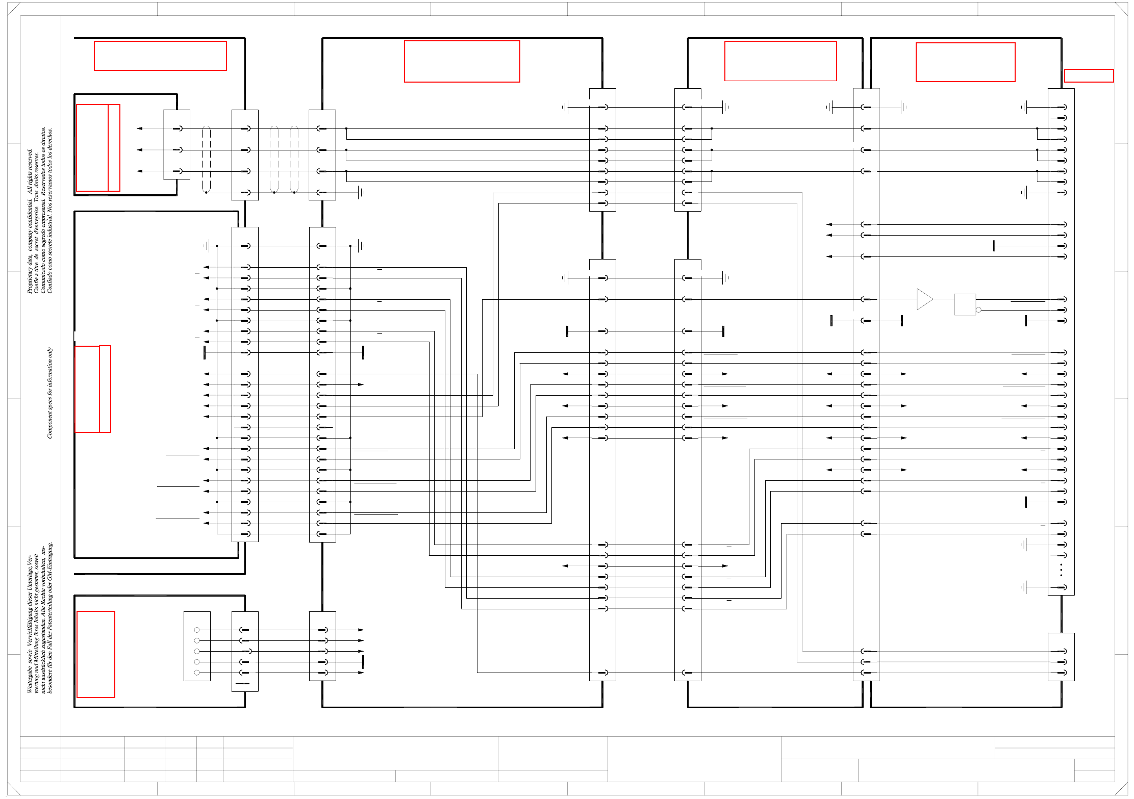
2 - 31
ZTH012-010101LD3 Z2 axis, TwinHead, P&P module 2, gantry 1, HF (Sh. 3 of 4)
28a,c
32a,c
30a,c
20a,c
18c
26c
24a,c
22c
16c
12c
14c
12A
10c
X1tv
8c
10A
8A
6A
6c
Servo amplifier
SDS 60/1.0 Z1-01
00353446-xx A10 (th)
12
6
10
11
9
7
8
3
4
5
1
2
X2tv
6
X5tv
5
4
3
1
2
13
16
17
18
14
15
19
20
n.u.
n.u.
n.u.
n.u.
J²t
PE
Servo Enable +
Servo Enable -
Servo Ready
Inom W
AGND
Inom U
Link voltage impressed
ADR2
ADR1
ADR3
ADR4
X3tv
Z1 motor W
Z1 motor V
Z1 motor U
03002163-W4
(Cable)
20
18
19
17
15
16
X6to
4
5
6
=
Date
Check.
Stand.
Author
Sheet
Orig. Repl. f. Repl. byNameDateModifiedStatus
Sh.
+
2
F
3
F
8
A
2
D
3
C
B
A
5
B
41
E
5
41
Z2 axis, TwinHead, P&P module 2
Function st.
C
D
E
678
76
1.
1.
1.
22.09.05
22.09.05
22.09.05
22.09.2005
Hi
ZTH012_HF-010101LD3
3
4
Hi
Hi
Hi
Product st.
Document st.
SIPLACE HF series
ZTH012_HF-010101LD3_SH03.DWG
CAD file :
Mat. no. :
18a
7
bk
wh
bk
16
25
23
n.u.
(W1)
(W1)
(W1)
(W1)
(W1)
(W2)
(W2)
gnye
Z/DP+ link voltage
Star+ link voltage
PE
Z/DP- link voltage
Vin_axis+
Vin_axis-
Z/DP+
4e
4f
3e
4b
4d
4c
4a
3f
X4wo
3b
vi3d
3c
3A
X3wo:Z28, X2wo:Z28
X3wo:D30, X2wo:Z30
(DC/DC converter)
(DC/DC converter)
12
vi
wh
HF
Star+
bn
A&D EA
s
bu
or
wh
X23
X21
13
Power supply
00354626-xx
X13
1
1
03009786-xx W1+W2
(Cable)
4c
4a
2a
2c
-15V
+15V
GND
ADR1
ADR2
ADR3
ADR4
Link voltage impressed
Servo Ready
AGND
Inom W
Inom U
Servo Enable
J²t
R31
L3
L2
R21
L1
R11
Z1 motor V
Z1 motor U
Z1 motor W
Gantry 1
C1
R12
R22
C2
R32
C3
Z/DP+ link voltage
Star+ link voltage
Star+
42
44
43
X21
41
bn
rd
bk
vi
bu
or
wh
142
3
bn
vi11
PE
1
6
4
2
4
3
9
1
2
3
7
12
11
10
9
8
13
14
PE
Flat ribbon cable
20x0.09mm²
X5wo
3d
3e
3c
3b
3A
4a
4d
4b
4c
3f
4e
4f
A35 (tv)
00353484-xx
Z2 axis / TwinHead / P&P module 2
Servo backplane
n.u.
n.u.
Link voltage impressed
AGND
Inom W
Inom U
n.u.
Servo Ready
n.u.
Servo Enable -
Servo Enable +
A48 (to)
Axis distributor I/O
00353487-xx
1
2
3
00353449-xx
5V/15V
DC/DC converter
A17
X2wo
d6
d10
or +15V (Servo)
bu -15V (Servo)
Sheet 4 / B7
Sheet 2 / A2
n.u.
n.u.
n.u.
n.u.
n.u.
n.u.
n.u.
n.u.
X4tv
Z/DP+5
4
3
1
2
n.u.
n.u.
n.u.
n.u.
-15V
+15V
GND
See page 5-19
See page 3-7
See page 5-27
See page 5-22
See page 5-25
See page 5-25