C371346_375F2440A66FD1C882296D07948AE54C.pdf - 第14页
CM 108AH Highly Integrated USB Audio I/O Controller www .cmedia.com.tw Copyright© C-Media Electro nics Inc. R ev . 2.1 ︱ P age 14/27 7.1.4 USB Audio To pology Diagra m IT IT OT OT USB Out Microphone In Feature Unit (volu…
CM108AH
Highly Integrated USB Audio I/O Controller
www.cmedia.com.tw
Copyright© C-Media Electronics Inc. Rev. 2.1︱ Page 13/27
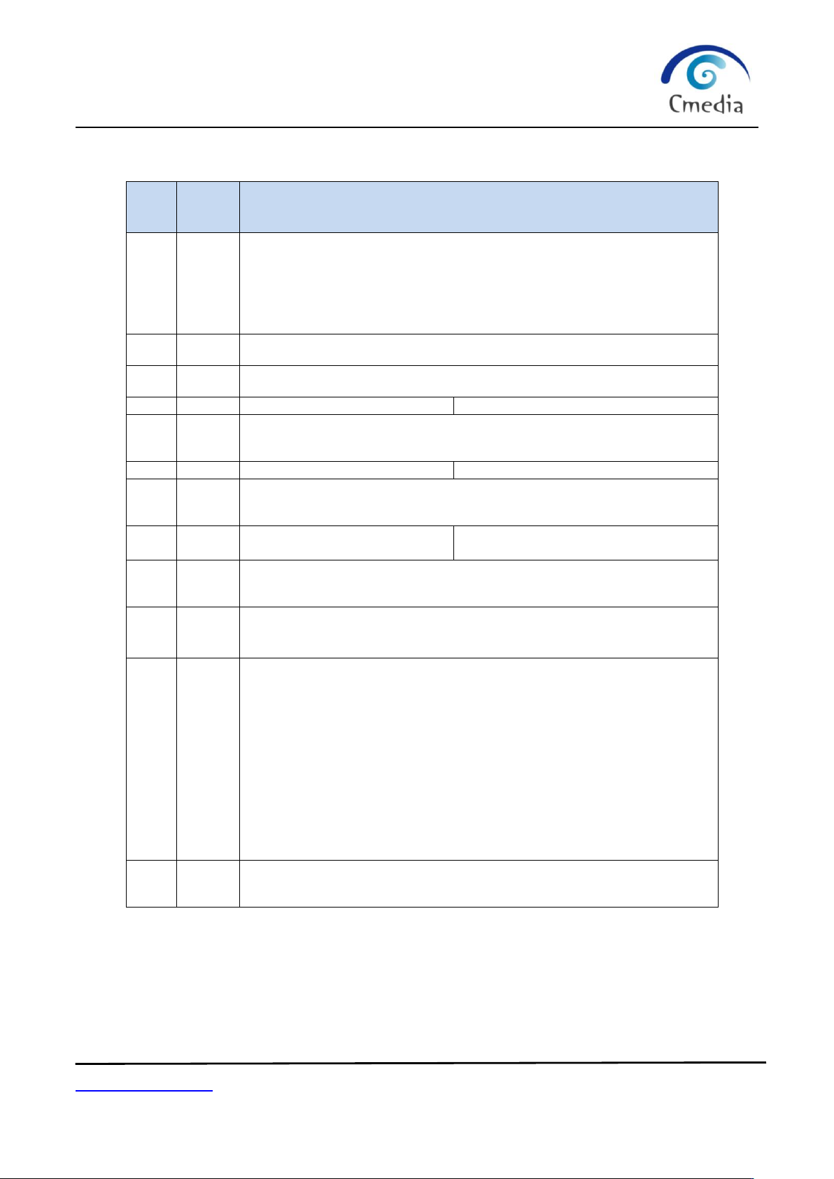
7.1.3 Content Format for EEPROM (93C46)
Addr
(Dec)
Addr
(Hex)
Description
0
0x00
Magic Word
0x670X where X = bit 4, 3, 2, 1
bit 3, value within address 0x2A,0x2B is valid 1: valid 0: invalid
bit 2, manufacture string enable 1: enable(default) 0: disable
bit 1, serial number enable control 1: enable 0: disable(default)
bit 0, product string enable control 1: enable(default) 0: disable
1
0x01
VID 2-byte
2
0x02
PID 2-byte
3
0x03
Serial number length (low byte)
Serial number first byte (high byte)
4
~
9
0x04
~
0x09
Serial number: 12 bytes
10
0x0A
Product string length (low byte)
Product string first byte (high byte)
11
~
25
0x0B
~
0x19
Product string: 30 bytes (default: USB PnP sound device)
26
0x1A
Manufacturer string length
(low byte)
Manufacturer string first byte
t
(high byte)
27
~
41
0x1B
~
0x29
Manufacturer string: 30 bytes (default: C-Media Electronics Inc.)
42
0x2A
bit 15 ~ 8 DAC initial volume (7-bit) max: 0x02 min: 0x4a
bit 7 ~ 0 ADC initial volume (5-bit) max: 0x00 min: 0x78
43
0x2B
bit 15 ~ bit 9 <reserved>
bit 8 Shutdown DAC analog - 1: shutdown, 0: active (default)
bit 7 Total power control - 1: enable, 0: disable (default)
bit 6 Reserved, should be 0
bit 5 MIC high pass filter - 1: enable (default), 0: disable
bit 4 ADC synchronization mode - 1: enable, 0: disable (default)
bit 3 MIC BOOST - 1: enable (default), 0: disable
bit 2 DAC output terminal property set to SPK or HP
1: Headset, 0: Speaker (default)
bit 1 HID - 1: enable (default), 0: disable
bit 0 Remote wakeup enable/disable
1: enable, 0: disable (default)
44
~
END
0x2C
~
END
<reserved>
CM108AH
Highly Integrated USB Audio I/O Controller
www.cmedia.com.tw
Copyright© C-Media Electronics Inc. Rev. 2.1︱ Page 14/27
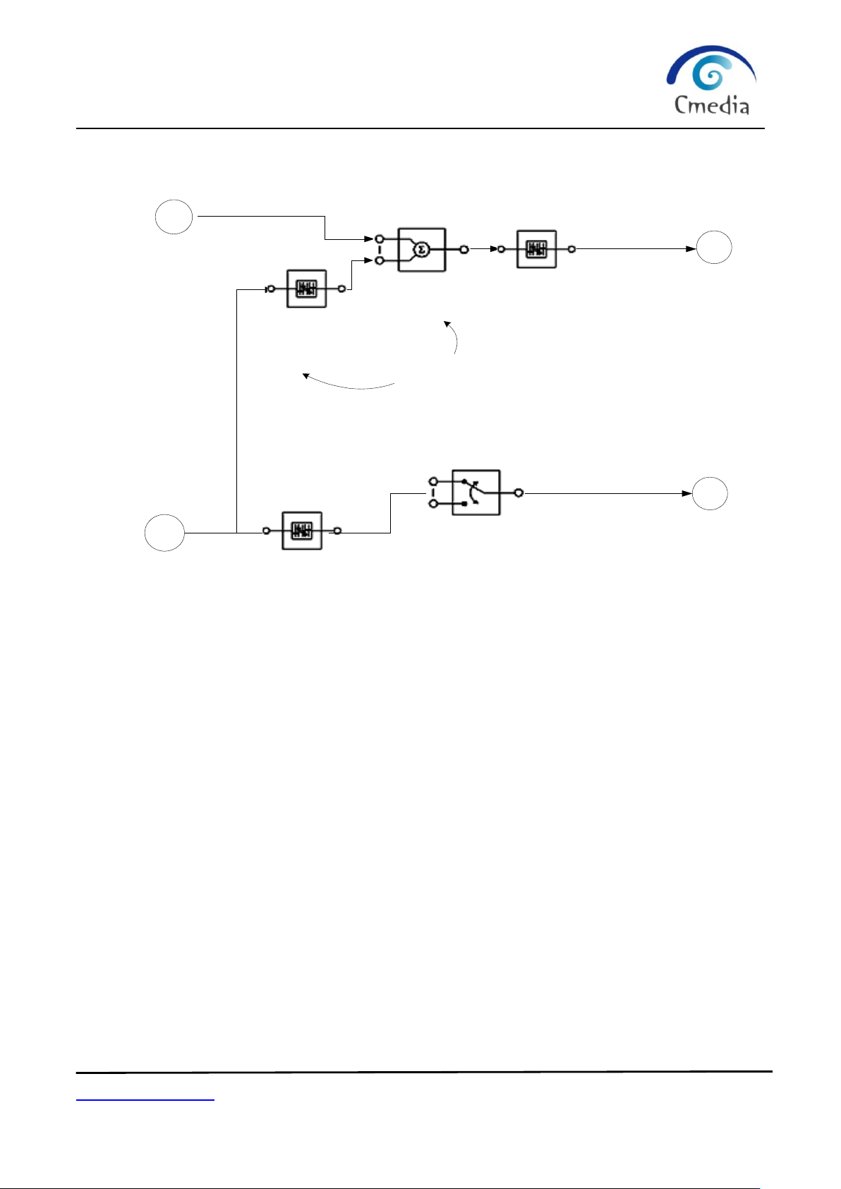
7.1.4 USB Audio Topology Diagram
IT
IT
OT
OT
USB Out
Microphone In
Feature Unit
(volume) (mute)
Speakerout
USBIN
Feature Unit
(volume) (mute)
ID = 01
ID=02
ID= 0A
ID = 09
ID = 06
ID = 07
Feature Unit
(volume) (mute)
ID = 0D
Mixer Unit
ID = 0F
selector Unit
ID = 08
enable or disable by
MSEL pin
CM108AH
Highly Integrated USB Audio I/O Controller
www.cmedia.com.tw
Copyright© C-Media Electronics Inc. Rev. 2.1︱ Page 15/27
7.2 Jumper Pins and Mode Setting:
The CM108AH can be configured via several jumper pins. These jumper pin settings affect both USB descriptors
and USB audio topology.
7.2.1 MODE Pin and MSEL Pin
If the MODE pin is pushed up to 3.3V (speaker mode), a playback-only function is activated and no recording
function is declared to the host. At this setting, t h e MSEL pin is ignored and only one input terminal, one
output terminal and one feature unit is declared in the USB audio topology.
If the MODE pin is pulled low (headset mode), a full-duplex playback and recording function is reported to the
host. The MSEL pin setting activates one mixer unit and one feature unit.
When MSEL = 1, the mixer is enabled (AA-path enabled), but with default mute setting
When MSEL = 0, the mixer is disabled (AA-path disabled)
The above USB audio topology (7.1.4) is an example of headset mode with enabled mixer.
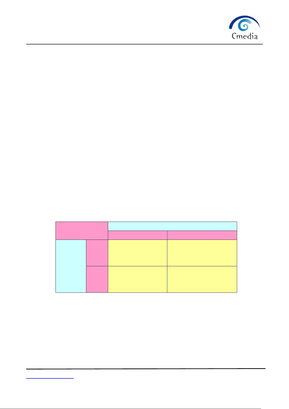
7.2.2 MODE Pin and PWRSEL Pin
The PWRSEL pin affects the power configuration of the CM108AH. Together with the MODE pin, there are a
total of 4 programmable combinations.
Combinations
MODE
3.3V
GND
PWRSEL
3.3V
Speaker mode:
Playback only
(100mA self-powered)
Headset mode:
Playback and recording
(100mA Bus-powered)
GND
Speaker mode:
Playback only
(500mA Bus-powered)
Headset mode:
Playback and recording
(500mA Bus-powered)
USB Audio Topology Diagram