00197190-03_VD_SIPLACE_Pro_10_1_SP1_DE_EN - 第18页
SIPLAC E Pro V10. 1 SP1 / Softwar e Version Desc ripti on Ausgabe 02/2013 Edit ion 18 5.4.1 Behav ior at Pick - up Errors If a com ponent is rejected by SI PLACE Vis ion it will b e put bac k in th e tra y as def ault. I…
SIPLACE Pro V10.1 SP1 / Software Version Description Ausgabe 02/2013 Edition
17
5.4 New TrayStak Feeder AX Feeder Type
The new TrayStak Feeder AX feeder type is supported on the X4i S placement machine on the
locations 2 and 3 for CPP (Collect&Place + Pick&Place) placement heads.
The TrayStak Feeder AX has one level with a waffle-pack tray for which the size is defined in the
setup, and a stacked inventory of further waffle-pack trays that obeys the FIFO rule. The current
waffle-pack tray cannot be exchanged by another tray of the inventory until all components have
been picked up.
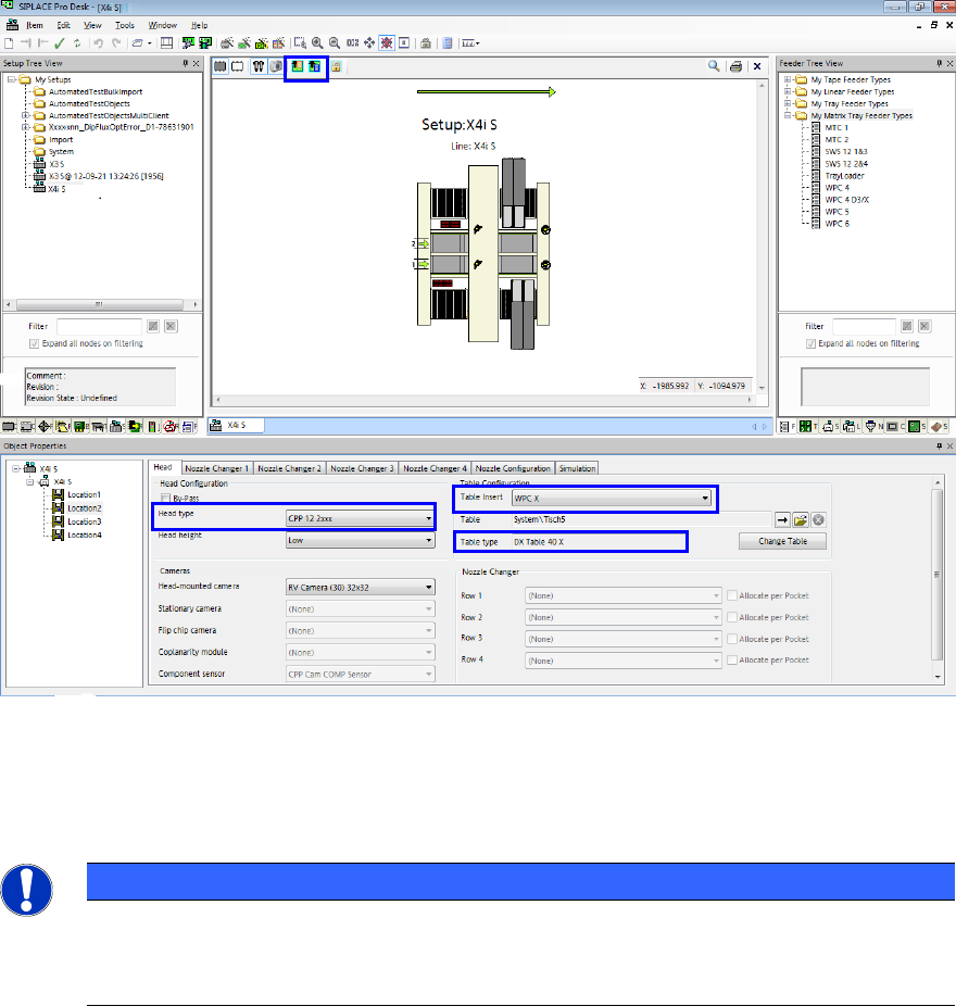
To set up the TrayStak Feeder AX, a table of type DX Table 40 X has to be configured in SIPLACE
Pro Desk on the locations 2 and 3. Additionally, the WPC X table insert has to be selected on these
locations in order to release the traveling range of the placement head for the feeder.
Figure 4-1: Configuring TrayStak Feeder AX
Head type, Table Insert and Table type have to be respectively set for Location 2 and Location 3.
Thereafter, the TrayStak Feeder has to be drawn from the Feeder Tree View to Location 2 and
Location 3 in the setup.
NOTICE
Positioning the Feeders
The tray has to be completely positioned in the travel range (visible via the marked
Show / Hide Traveling ranges buttons).
If 2 TrayStak Feeder AX are installed together with an LDU-X (Linear Dipping Unit), the table has to
be manually selected in the station software.
SIPLACE Pro V10.1 SP1 / Software Version Description Ausgabe 02/2013 Edition
18
5.4.1 Behavior at Pick-up Errors
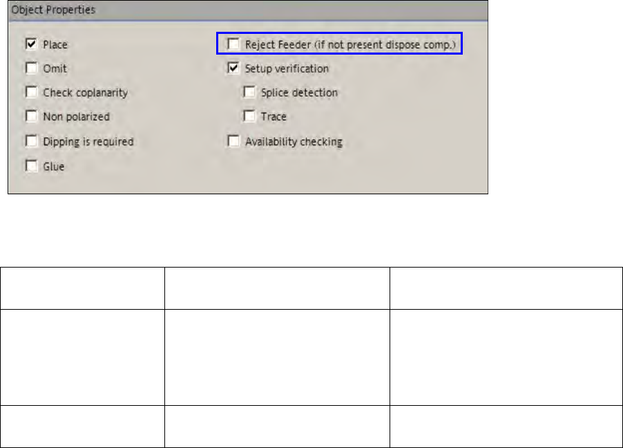
If a component is rejected by SIPLACE Vision it will be put back in the tray as default. If the
component shall be rejected in error cases, the Reject Feeder (if not present dispose comp.)
option has to be enabled for the component. If no reject conveyor is present, the component will be
disposed of in the reject bin.
Figure 4-2: Rejecting component
The behavior at pick-up errors is explained in the following table.
Reject Conveyor
Option
Tape / Linear Feeders Tray Feeders
enabled If the reject conveyor is present,
the component will be put on it.
If no reject conveyor is present,
the component will be disposed of
in the reject bin.
If the reject conveyor is present,
the component will be put on it.
If no reject conveyor is present, the
component will be disposed of in
the reject bin.
disabled The component will always be
disposed of in the reject bin.
The component will be put back
into an empty division of the tray.
Table 4-1: Behavior at pick-up errors
Please also refer to the restrictions in chapter 5.

SIPLACE Pro V10.1 SP1 / Software Version Description Ausgabe 02/2013 Edition
19
5.5 Placement of Tall Components with Very High Force Pick&Place
Head and WPC5 / WPC6
Components up to a height of 30mm can be placed with a force of 70N. The WPC5 can transport
such components as of serial number 1485, the WPC6 as of serial number C1486.
For this purpose, the new Very High Force Pick&Place Head (named VHF P&P head in the
following) has been developed.The VHF P&P head is derived from the existing Twin Head but has
one segment only.
NOTICE
WPC6 – Tall Components as of Level 4 Only!
Due to the refill module, components > 25mm cannot be positioned on the levels 1 – 3
and 27 – 28 on the WPC6. The levels 4 –
28 will be automatically set up by the SIPLACE
Pro Optimizer. The levels 1 – 3 have to be manually blocked by the operator.
The VHF P&P head is supported on the SX1/SX2 V2 placement machine. In addition, a PCB
camera is needed that is installed at another, higher position.
For placement with the mentioned maximum values, the new short 508 nozzle type is available. It
is based on the 518 nozzle type but is shorter. The 508 nozzle type can also be used by the Twin
Head.
In SIPLACE Pro Desk, two new travel profiles are available for the VHF P&P head:
36: Max force 70N
37: Max force 70N Slow
5.6 SIPLACE GlueFeeder Feeder Type
The following improvements are available for the SIPLACE GlueFeeder feeder type:
– The time calculation for the glue procedure has been adjusted and optimized in SIPLACE Pro.
– SIPLACE Vision checks if the glue dot positions are placed within the component shape of the
component. When the user starts an integry check for the component or the optimization for a
recipe in which the component shape of this component is used, an error message will be
displayed if the glue dot positions are placed outside the component shape.
Detailed information about SIPLACE GlueFeeder can be found in the corresponding User Manual,
item no. [00197218-xx], and in the Online Helps for SIPLACE Vision and the station software.