Specification SIPLACE X-Series规格说明书1 - 第64页
64 Standard List The following functions are cont ai ned as standard in the SIPLACE X-serie s without any extra charge: Standard features X4 X3 X2 V acuum sensor X X X Force measurement X X X Force sensor X X X Fiducial …
63
Technical Data
Transport and Delivery Configuration
Description
Within Europe, the machine
is delivered on a robust
wooden pallet. If sent over-
seas, the machine is pack-
aged in a wooden crate.
Configuration when deliv-
ered
• The extension kit on the
PCB input side with the
computer unit or the box
PC are disconnected from
the basic machine.
• All electrical cables to the
basic machine are discon-
nected.
• The track on the single
conveyor is set to a width
of 210 mm. On the dual
conveyor, the default width
of lane 1 is 100mm and of
lane 2 is 210 mm.
• The input conveyors of the
single and dual conveyor
are dismantled. The elec-
trical cables to the con-
veyor motors and light
barriers are disconnected.
• Both keyboards and the
monitors are discon-
nected.
• The main fault indicator is
dismantled.
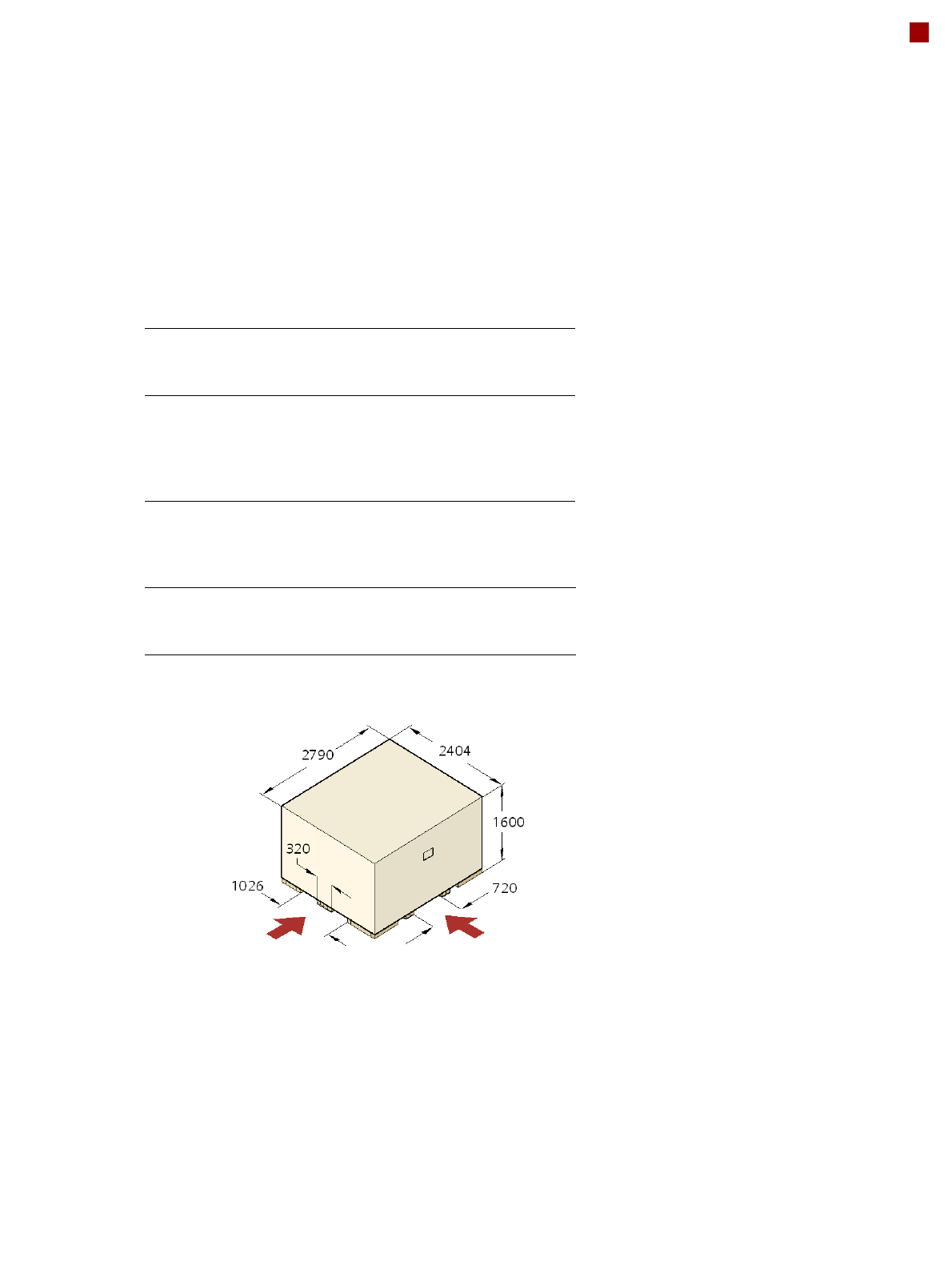
Transport dimensions and weight
Means of transport
A fork-lift truck with the following specification will be needed to
carry the machine in its crate:
Length
Width
Height
2404 mm
2790 mm
1600 mm
Weight
X4
X3
X2
Dispatch Dispatch
within Europe overseas
4004 kg 4504 kg
3980 kg 4420 kg
3836 kg 4336 kg
Fork length
Lifting power
Clear fork width
min. 1800 mm
min. 6000 kg
min. 350 mm
Engagement point
for the fork-lift
Engagement point
for the fork-lift

64
Standard List
The following functions are contained as standard in the SIPLACE X-series without any extra
charge:
Standard features
X4 X3 X2
Vacuum sensor X X X
Force measurement X X X
Force sensor X X X
Fiducial & ink spot detection X X X
Nozzle changer for the TwinHead X X X
Set of TwinHead nozzles X X X
Set of standard nozzles per head X X X
Single conveyor, stationary conveyor side right X X X
Single conveyor, stationary conveyor side left X X X
Wide board
configuration
XXX
PCB buffer function on conveyor X X X
PCB stopper laser light barrier X X X
Automatic electrical PCB width adjustment X X X
Operation on both sides X X X
LCD monitors X X X
Touch-screen monitor X X X
indicator lamps X X X
Tape cutter with reject bin X X X
Tape separating plates X X X
01005 placement X X X
Magnetic pin support X X X

65
List of Options
Available options X4 X3 X2 Notes
Bypass function X X X
Flexible dual conveyor
fixed side right
XXX
Flexible dual conveyor
fixed side left
XXX
PCB alignment, single conveyor X X X
PCB alignment, dual conveyor X X X
Long board X X X
Mechanical stopper X X X
1D PCB barcode scanner X X X Restrictions for a PCB longer than
430 mm
2D PCB barcode scanner X X X Restrictions for a PCB longer than
430 mm
PCB barcode scanner assembly kit X X X
20-nozzle Collect&Place head X X X In the two-gantry area, only in
combination with another 20-
nozzle Collect&Place head
12-nozzle Collect&Place head X X X
High-resolution component camera,
type 29, for C&P12
XXX
C&P12 component sensor X X X
0201 package X X X
6-nozzle Collect&Place head X X X
TwinHead X X X
High-Force Head X X X
Stationary component camera, type 25,
16 x 16, digital
X X X For the TwinHead or High-Force
Head only
Vision Teaching Station X X X
Coplanarity module n.a.
a
a) Not applicable.
X X For the TwinHead or High-Force
Head at location 3 only
Nozzle Changer X X X Depending on the placement head
Sensor for the component reject bin X X X
SIPLACE X component changeover
table
XXX
Splice detection for X feeder modules X X X
Waffle-pack tray holder
SIPLACE X
X X X Can be used at locations 2 and 4
but only with the SIPLACE X com-
ponent changeover tables; not in
combination with the C&P20
placement head