User Manual E-by-SIPLACE 用户手册.pdf - 第113页
User manual E by SIPLACE 3 Technical data and assemblies From software version SC 712.1 Edition 05/2019 3.3 Dimensions an d weight 113 3.3.4 Maneuvering distance for the changeover table 3 Fig. 3.3 - 7 Maneuvering distan…
3 Technical data and assemblies User manual E by SIPLACE
3.3 Dimensions and weight From software version SC 712.1 Edition 05/2019
112
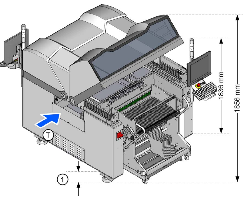
3.3.3 Height of the folded up protective cover
3
Fig. 3.3 - 6 Height of the folded-up protective cover - dimensions in millimeters
The specified dimensions refer to the max. PCB conveyor height of 950 mm.
(1) The height varies according to the set PCB conveyor height
– for PCB conveyor height 900 mm = 137 mm ± 15 mm: 1806 mm
– for PCB conveyor height 930 mm = 167 mm ± 15 mm: 1836 mm
– for PCB conveyor height 950 mm = 187 mm ± 15 mm: 1856 mm
User manual E by SIPLACE 3 Technical data and assemblies
From software version SC 712.1 Edition 05/2019 3.3 Dimensions and weight
113
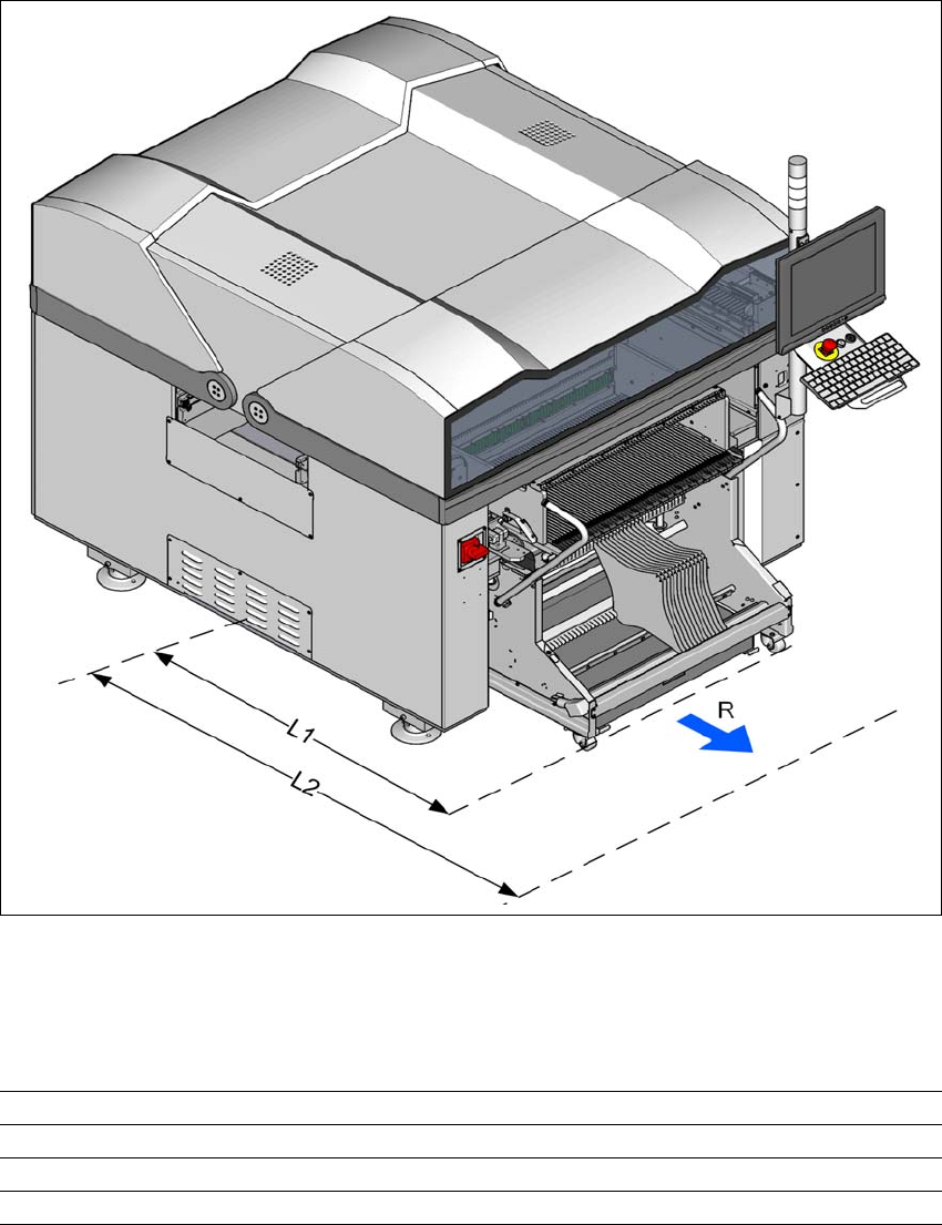
3.3.4 Maneuvering distance for the changeover table
3
Fig. 3.3 - 7 Maneuvering distance for the changeover table on E by SIPLACE machine
The maneuvering radii "R" for the changeover table in E by SIPLACE machines is:
3
3
Location 1 / Location2
Maneuvering radius R 700 mm
Distance L1: Machine center to outer edge of changeover table 1205 mm
Distance L2: Machine center to wall 1905 mm
3 Technical data and assemblies User manual E by SIPLACE
3.3 Dimensions and weight From software version SC 712.1 Edition 05/2019
114
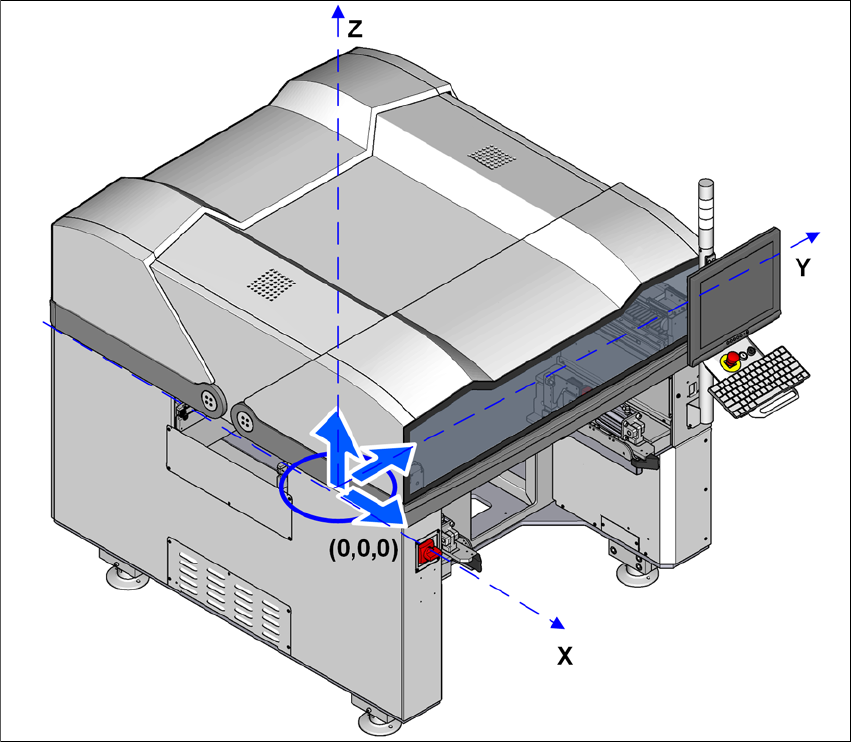
3.3.5 Center of gravity
3.3.5.1 Machine center of gravity
3
Fig. 3.3 - 8 Center of gravity for E by SIPLACE machines in millimeters
X coordinate 0 mm
Y coordinate 0 mm
Z coordinate 721 mm
These center of gravity coordinates relate to placement machines with a PCB conveyor height of
900 mm.