User Manual E-by-SIPLACE 用户手册.pdf - 第118页
3 Technical data and assemblies User manual E by SIPLACE 3.5 Placement head From software version SC 712.1 Edition 05/201 9 118 3 Fig. 3.5 - 2 SIPLACE CP14 - function group part 2 (1) Component camera, type 2 3 GigE (2) …
User manual E by SIPLACE 3 Technical data and assemblies
From software version SC 712.1 Edition 05/2019 3.5 Placement head
117
3.5 Placement head
3.5.1 SIPLACE CP14 for very high speed placement
Item no. 03109887-xx, SIPLACE CP14 (without camera)
Item no. 03105195-xx, Component camera, type 23 GigE
3
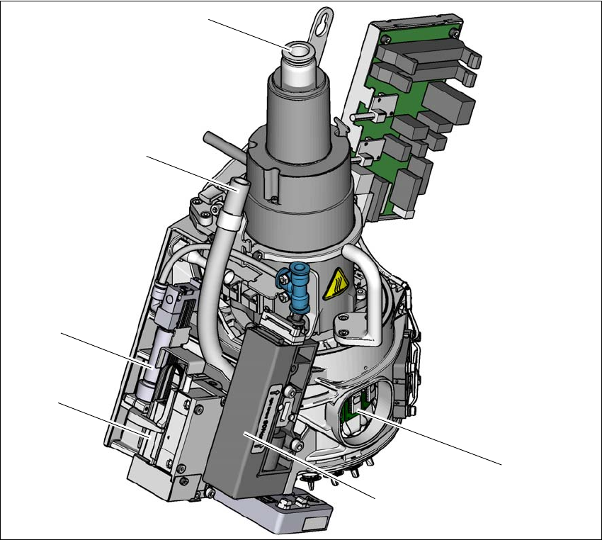
Fig. 3.5 - 1 SIPLACE CP14 - function group part 1
(1) DP drive, 14 drives
(2) Pressure control valve
(3) Z motor (linear motor)
(4) Return cylinder
(5) Line for the exhaust air from the pressure control valve (2)
(6) Compressed air connection for 14 Venturi nozzles in the pickup/placement and holding circuit
(1)
(2)
(3)
(4)
(5)
(6)
3 Technical data and assemblies User manual E by SIPLACE
3.5 Placement head From software version SC 712.1 Edition 05/2019
118
3
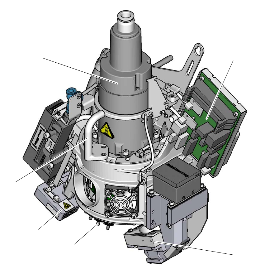
Fig. 3.5 - 2 SIPLACE CP14 - function group part 2
(1) Component camera, type 23 GigE
(2) Star with 14 nozzles
(3) Component sensor
(4) Handle
(5) Star motor
(6) Intermediate distributor board
(1)
(2)
(3)
(4)
(5)
(6)

User manual E by SIPLACE 3 Technical data and assemblies
From software version SC 712.1 Edition 05/2019 3.5 Placement head
119
3.5.1.1 Description
The SIPLACE CP14 functions according to the Collect&Place principle, i.e. fourteen components
are picked up by the placement head within a single cycle. At the pick-up and placement position
the component sensor checks that the component is present at the nozzle. On their way to the
placement position the components are optically centered and rotated into the required placement
angle. Finally forced air sets down the component gently and accurately on the board.
The SIPLACE CP14 makes a significant increase in the placement head performance possible
and therefore in the performance of the placement machine. The compact design of the SIPLACE
CP14 also facilitates very short cycle times. In this case, the star axis is at an angle to the PCB
level. This geometry allows the segments to be arranged in a very small space.
The component camera is still integrated into the SIPLACE CP14. This saves additional traveling
distances to external centering cameras. Each segment also has its own DP drive for rotating the
nozzle. The nozzles are therefore no longer rotated into the correct position at a single head sta-
tion. They can be rotated into their placement position at any time and independently of one an-
other.
Each segment has a separate vacuum generator. This greatly reduces the time taken to switch
between vacuum and air kiss. It also allows a vacuum check to be carried out in the holding circuit
for each individual nozzle.
The Z drive for the segments is implemented with a linear motor with linear path measuring sys-
tem, and is thus extremely precise. In the pick-up/placement position, the Z drive moves the seg-
ments up or down in the vertical direction.
3.5.1.2 Sensor for the component reject bin
Item no. 03103405-xx Sensor for component reject bin
The sensor for the component reject bin monitors whether the reject bin is seated correctly in its
mount.
– If the reject bin was not inserted correctly, the machine cannot be started.
– If the reject bin jumps out of its mount during the placement process, the machine is stopped
immediately to avoid a head crash.
Each reject bin is monitored by a separate sensor.
3.5.1.3 Operation with a vacuum pump
The SIPLACE CP14 use a vacuum pump for more efficient vacuum generation (see Section 3.5.4,
page 129).