User Manual E-by-SIPLACE 用户手册.pdf - 第122页
3 Technical data and assemblies User manual E by SIPLACE 3.5 Placement head From software version SC 712.1 Edition 05/201 9 122 3 Fig. 3.5 - 4 SIPLACE CP12 - Function groups, part 2 3 (1) Intermediate distributo r board …
User manual E by SIPLACE 3 Technical data and assemblies
From software version SC 712.1 Edition 05/2019 3.5 Placement head
121
3.5.2 SIPLACE CP12 for high-speed placement
Item no. 03082532-xx, SIPLACE CP12
Item no. 03101672-xx, Component camera, type 30 GigE
3
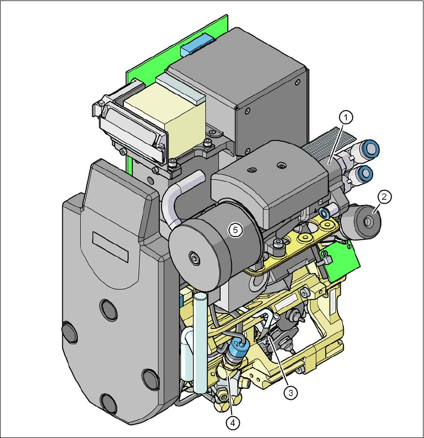
Fig. 3.5 - 3 SIPLACE CP12 - Function groups, part 1
3
(1) Vacuum generator
(2) Turning station, DP axis
(3) Star with 12 sleeves, star axis
(4) Forced air valve
(5) Silencer
3 Technical data and assemblies User manual E by SIPLACE
3.5 Placement head From software version SC 712.1 Edition 05/2019
122
3
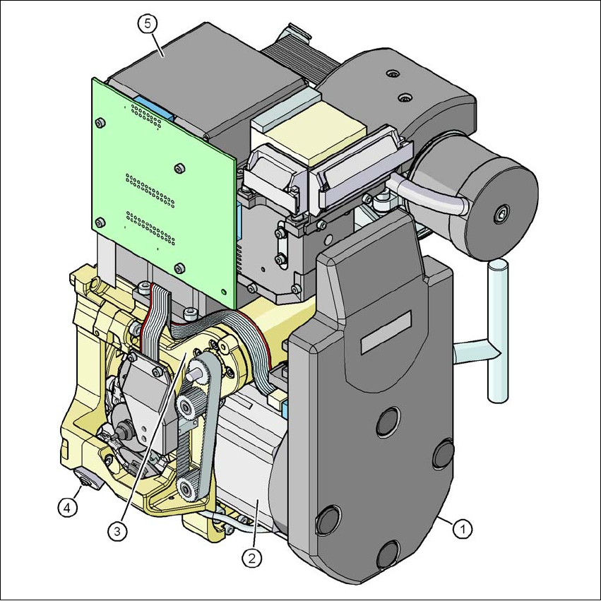
Fig. 3.5 - 4 SIPLACE CP12 - Function groups, part 2
3
(1) Intermediate distributor board (beneath the cover)
(2) Star drive - DR motor
(3) Z axis motor
(4) Valve adjustment drive
(5) Component camera, type 30 GigE
User manual E by SIPLACE 3 Technical data and assemblies
From software version SC 712.1 Edition 05/2019 3.5 Placement head
123
3.5.2.1 Description
The SIPLACE CP12 works on the Collect&Place principle. This means that, within each cycle,
twelve components are picked up by the placement head, are optically centered on the way to the
placement position and are rotated into the required placement angle. They are then set down
gently and accurately on the PCB with a blast of air. The twelve nozzles on SIPLACE CP12 turn
about a horizontal axis, in contrast to conventional chip shooters. This does not simply save
space: the small diameter means that substantially smaller centrifugal forces occur in comparison
to conventional chip shooters. This largely eliminates the risk of components slipping during trans-
portation.
And there is yet another benefit: the cycle time of the SIPLACE CP12 is the same for all compo-
nents, which means that the placement rate is not dependent on the component size.
3.5.2.2 Sensor for the component reject bin
Item no. 03103405-xx Sensor for component reject bin
The sensor for the component reject bin monitors whether the reject bin is seated correctly in its
mount.
– If the reject bin was not inserted correctly, the machine cannot be started.
– If the reject bin jumps out of its mount during the placement process, the machine is stopped
immediately to avoid a head crash.
Each reject bin is monitored by a separate sensor.