User Manual E-by-SIPLACE 用户手册.pdf - 第132页
3 Technical data and assemblies User manual E by SIPLACE 3.5 Placement head From software version SC 712.1 Edition 05/201 9 132 3.5.5.1 Description This sophisticated placement hea d consists of two placement hea ds of t…
User manual E by SIPLACE 3 Technical data and assemblies
From software version SC 712.1 Edition 05/2019 3.5 Placement head
131
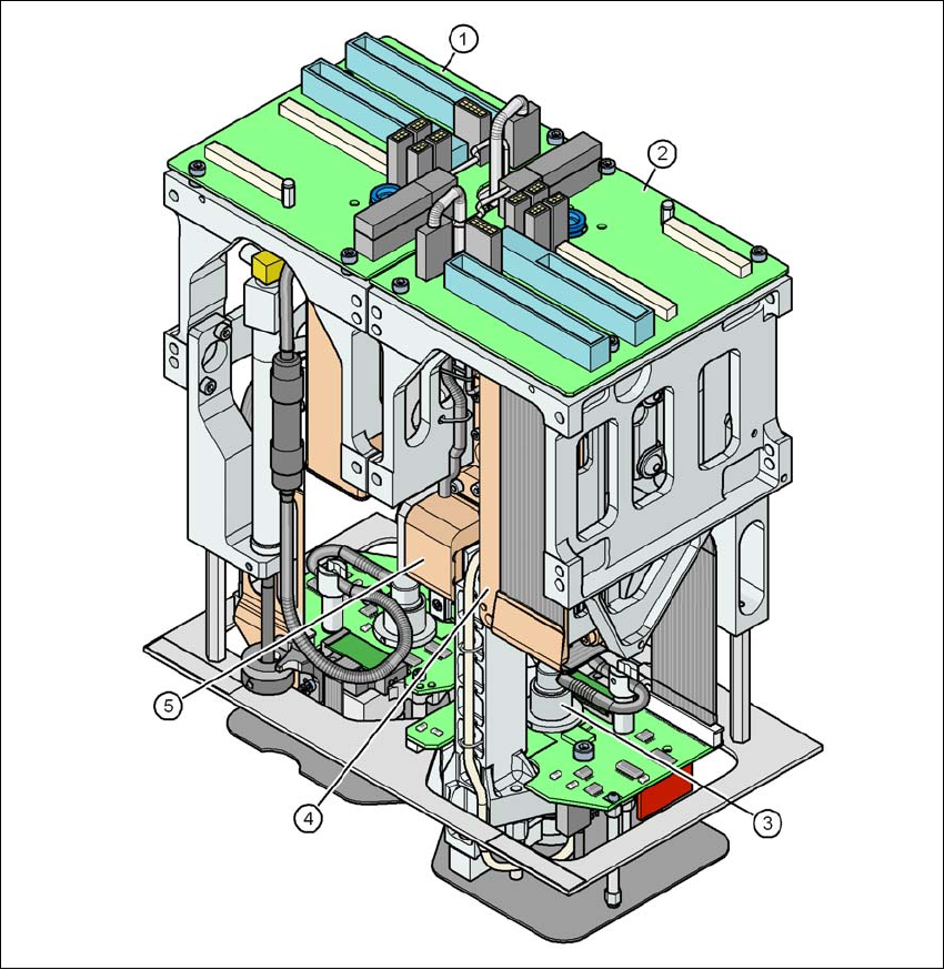
3.5.5 SIPLACE TH for high precision IC placement
Item no. 03033629-xx SIPLACE TH
Item no. 03112312-xx Stationary component camera, type 36 GigE
3
Fig. 3.5 - 8 SIPLACE TH for high precision IC placement
(1) Pick&Place module 1 (PP1) - the SIPLACE TH consists of 2 Pick&Place modules
(2) Pick&Place module 2 (PP2)
(3) DP axis
(4) Z axis drive
(5) Incremental distance measuring system for the Z axis
3 Technical data and assemblies User manual E by SIPLACE
3.5 Placement head From software version SC 712.1 Edition 05/2019
132
3.5.5.1 Description
This sophisticated placement head consists of two placement heads of the same type coupled to-
gether. Both heads work using the Pick&Place principle. The SIPLACE TH is suitable for process-
ing complex and large components. Two components are picked up by the placement head,
optically centered on the way to the placement position and rotated into the necessary placement
angle. They are then placed gently and accurately onto the PCB with a controlled blast of air.
The nozzles of type 5xx/5xxx have been developed for the SIPLACE TH. With an adapter you can
also use the nozzles of type 4xx, 8xx and 9xx.

User manual E by SIPLACE 3 Technical data and assemblies
From software version SC 712.1 Edition 05/2019 3.5 Placement head
133
3.5.5.2 Technical data
SIPLACE TH
with stationary
camera type 36 GigE
(Standard)
with stationary
camera type 33 GigE
(Fine pitch)
with stationary
camera type 25 GigE
(Flip chip)
Component range
*a
0603 to SO, PLCC, QFP,
BGA, special compo-
nents, bare dies, flip-
chips
0402 to SO, PLCC, QFP,
BGA, special components,
bare dies, flip-chips
0201 to SO, PLCC, QFP,
sockets, plugs, BGA, spe-
cial components, bare dies,
flip-chips, shields
Component specs
Max. height
Min. lead pitch
Min. lead width
Min. ball pitch
Min. ball diameter
Min. dimensions
Max. dimensions
Max. weight
*b
25 mm
0.4 mm
0.24 mm
0.56 mm
0.32 mm
1.6 x 0.8 mm²
32 x 32 mm²
(single measurement)
For use with two nozzles:
50 mm x 50 mm or
69 mm x 10 mm
For use with one nozzle
(multiple measurement):
78 mm x 78 mm or
110 mm x 10 mm
up to 200 mm x 110 mm
(with restrictions)
100 g
25 mm
0.3 mm
0.15 mm
0.35 mm
0.2 mm
1.0mm x 0.5mm
55 mm x 45 mm
(single measurement)
For use with two nozzles:
50 mm x 50 mm or 69 mm
x 10 mm
For use with one nozzle
(multiple measurement):
78 mm x 78 mm or
110 mm x 10 mm
up to 200 mm x 110 mm
(with restrictions)
100 g
25 mm
0.25 mm
0.1 mm
0.14 mm
0.08 mm
0.6 mm x 0.3 mm
16 mm x 16 mm
(single measurement)
55 mm x 55 mm
(multiple measurement)
100 g
Programmable set-down
force
1.0 N - 15 N 1.0 N - 15 N 1.0 N - 15 N
Nozzle types
*c
5xx (standard)
4xx + adapter
8xx + adapter
9xx + adapter
5xx (standard)
4xx + adapter
8xx + adapter
9xx + adapter
5xx (standard)
4xx + adapter
8xx + adapter
9xx + adapter
Nozzle spacing for P&P
heads
70.8 mm 70.8 mm 70.8 mm
X/Y accuracy
*d
± 50 µm/3σ ± 50 µm / 3σ ± 22 µm / 3σ
Angular accuracy ± 0.05°/3σ ± 0.05° / 3σ ± 0.05° / 3σ
Illumination level 6 6 6
Possible illumination level
settings
256
6
256
6
256
6
*)a Please note that the placeable component range is also affected by the pad geometry, the customer-specific standards, the
component packaging tolerances and the component tolerances.
*)b If standard nozzles are used
*)c Over 300 different nozzles and 100 gripper types are available, with an extensive nozzle database available online.
*)d The SIPLACE accuracy value is measured during the machine acceptance tests. It corresponds to the conditions set out in
the SIPLACE scope of service and supply.