User Manual E-by-SIPLACE 用户手册.pdf - 第139页
User manual E by SIPLACE 3 Technical data and assemblies From software version SC 712.1 Edition 05/2019 3.6 PCB conveyor system 139 3.6.3 Controlling and width adjustment 3.6.3.1 Controlling using the Single Functions me…
3 Technical data and assemblies User manual E by SIPLACE
3.6 PCB conveyor system From software version SC 712.1 Edition 05/2019
138
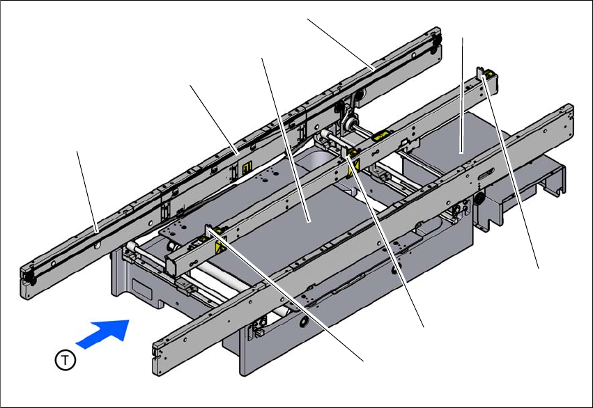
3.6.2 Design of the PCB single conveyor
3
Fig. 3.6 - 1 Design of the PCB single conveyor
(1) Input conveyor
(2) Processing conveyor
(3) Lifting table
(4) Output conveyor
(5) Conveyor control (under the cover)
(6) Output stopper
(7) Processing topper
(8) Input stopper
(1)
(3)
(4)
(2)
(5)
(7)
(8)
(6)
User manual E by SIPLACE 3 Technical data and assemblies
From software version SC 712.1 Edition 05/2019 3.6 PCB conveyor system
139
3.6.3 Controlling and width adjustment
3.6.3.1 Controlling using the Single Functions menu
The online help contains information on controlling the PCB conveyor system and on the Single
Functions menu.
3.6.3.2 Automatic width adjustment
When the command is received, the conveyor belts are set to the desired width.
See the Online Help for detailed information about changing the conveyor track width.
3 Technical data and assemblies User manual E by SIPLACE
3.6 PCB conveyor system From software version SC 712.1 Edition 05/2019
140
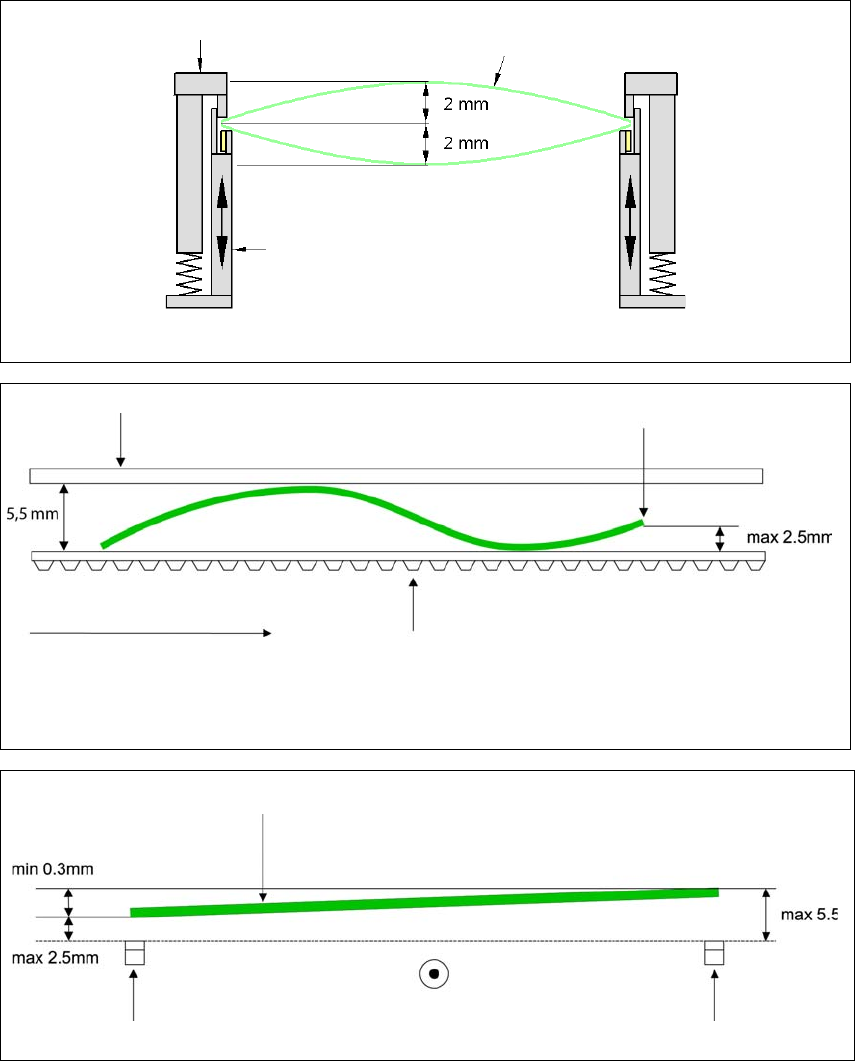
3.6.4 Definition of PCB warpage
3.6.4.1 PCB warpage on the conveyor
3
3
3
Movable clamping device
Fixed clamped edge
Movable clamping device
PCB
PCB warpage across the direction of travel max. 1 % of the PCB diagonal, but not exceeding 2 mm.
Fixed clamped edge
Conveyor belt
PCB transport direction
Front board edge
PCB warpage in direction of travel + PCB thickness < 5.5 mm.
Bending up of front board edge max. 2.5 mm.
Front board edge
Left conveyor belt
Right conveyor belt
PCB transport direction