User Manual E-by-SIPLACE 用户手册.pdf - 第14页
1 Introduction User manual E by SIPLACE 1.1 Single sided E by SIPLACE From software version SC 712.1 Edi tion 05/2019 14 1.1 Single sided E by SIPLACE 1.1.1 E by SIPLACE with chan ge over table on location 1 1 Fig. 1.1 -…

User manual E by SIPLACE 1 Introduction
From software version SC 712.1 Edition 05/2019
13
1 Introduction
This user manual is a manual or reference work for operating and setting up the E by SIPLACE
®
placement machines. This document is the original user manual.
The header of each chapter contains the release and software version, to which this manual ap-
plies.
The E by SIPLACE mid-speed SMT placement platform was developed especially for small and
medium-sized electronics production environments.
The E by SIPLACE placement machines are available in different variants and configurations:
– Single sided placement machine with fixed table or changeover table on location 1. There is
no component table for supplying components on location 2.
– Double sided placement machine with fixed table on location 1 and changeover table on lo-
cation 2.
– Double sided placement machine with changeover table on location 1 and location 2.
– Double sided placement machine with fixed table on location 1 and location 2.
Five head options can be configured to perfectly meet the production needs:
–SIPLACE CP14
–SIPLACE CP12
– SIPLACE CP12/PP
– SIPLACE CP6/PP
–SIPLACE TH
1 Introduction User manual E by SIPLACE
1.1 Single sided E by SIPLACE From software version SC 712.1 Edition 05/2019
14
1.1 Single sided E by SIPLACE
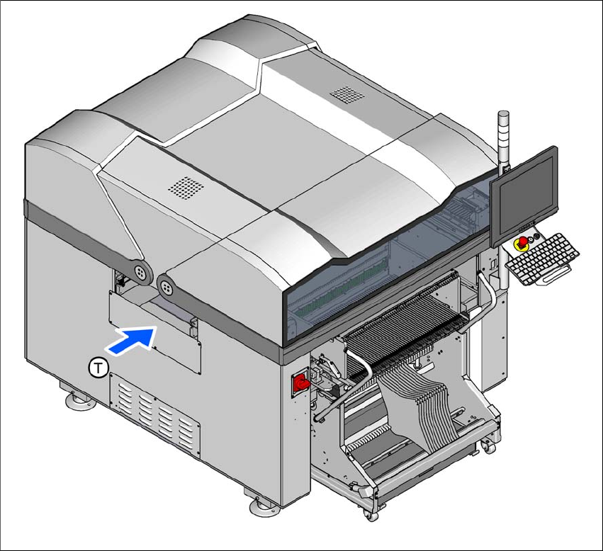
1.1.1 E by SIPLACE with change over table on location 1
1
Fig. 1.1 - 1 Single sided E by SIPLACE placement machine with change over table on location 1
(T) Direction of PCB transport

User manual E by SIPLACE 1 Introduction
From software version SC 712.1 Edition 05/2019 1.1 Single sided E by SIPLACE
15
The E by SIPLACE placement machines demonstrate
– High precision
– Placement performance up to the high end process range
– A wide ranging component range from 01005 components to a size of 200 mm x 110 mm.
Following placement methods are possible for processing the components:
– Collect&Place and
– Pick&Place
The E by SIPLACE placement machine consists one gantry. For an overview of the placement
head configuration, refer to section 3.1.1
from page 101.
These can be quickly and accurately positioned by linear motors, moving independently of one
another in the X and Y directions.
The E by SIPLACE machine supports the SIPLACE single conveyor.
There is a changeover table available on location 1 for supplying components. On location 2 is no
table for supplying components.