User Manual E-by-SIPLACE 用户手册.pdf - 第141页
User manual E by SIPLACE 3 Technical data and assemblies From software version SC 712.1 Edition 05/2019 3.6 PCB conveyor system 141 3.6.4.2 PCB warpage during placement 3 3 Changes in the surface position ar e automatica…
3 Technical data and assemblies User manual E by SIPLACE
3.6 PCB conveyor system From software version SC 712.1 Edition 05/2019
140
3.6.4 Definition of PCB warpage
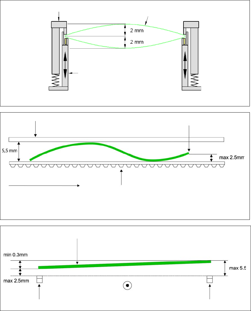
3.6.4.1 PCB warpage on the conveyor
3
3
3
Movable clamping device
Fixed clamped edge
Movable clamping device
PCB
PCB warpage across the direction of travel max. 1 % of the PCB diagonal, but not exceeding 2 mm.
Fixed clamped edge
Conveyor belt
PCB transport direction
Front board edge
PCB warpage in direction of travel + PCB thickness < 5.5 mm.
Bending up of front board edge max. 2.5 mm.
Front board edge
Left conveyor belt
Right conveyor belt
PCB transport direction
User manual E by SIPLACE 3 Technical data and assemblies
From software version SC 712.1 Edition 05/2019 3.6 PCB conveyor system
141
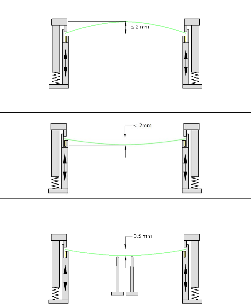
3.6.4.2 PCB warpage during placement
3
3
Changes in the surface position are automatically applied by the functions for learning the height.
3
3
PCB warpage up, max. 2 mm
PCB warpage down, max. 2 mm
0.5 mm
To avoid impairing the placement quality and speed, we recommend using a PCB support e.g. Smart Pin
Support so that the PCB warpage downwards does not exceed 0.5 mm.
3 Technical data and assemblies User manual E by SIPLACE
3.7 Vision system From software version SC 712.1 Edition 05/2019
142
3.7 Vision system
3.7.1 Structure
A component camera is integrated at each Collect&Place head (SIPLACE CP14/12/6). The com-
ponent camera, stationary, P&P type 33 GigE, type 36 GigE and type 25 GigE for the SIPLACE
TH/SIPLACE PP head is fixed to the machine frame.
The
component vision module
is used to determine:
– the precise position of the components at the nozzle and
– the geometry of the package form.
The
PCB vision module
uses fiducials on the PCBs to determine:
– the position of the PCB,
– its rotation angle
– and the PCB skew.
The PCB cameras are fixed to the bottom of the gantries. They use fiducials on the
feeder mod
-
ules
to determine the exact pick-up position of components, which is particularly important for
small components.