User Manual E-by-SIPLACE 用户手册.pdf - 第181页
User manual E by SIPLACE 4 Setting up and commissioning From software version SC 712.1 Edition 05/2019 4.2 Infrastructur e at the installation location 181 4.2.3.4 Mains connection - delivery configuration The main power…
4 Setting up and commissioning User manual E by SIPLACE
4.2 Infrastructure at the installation location From software version SC 712.1 Edition 05/2019
180
4.2.3.1 Danger notes
4
4.2.3.2 Checking the main power supply
Check whether the power supply complies with the prescribed machine specifications (see table
in section 3.2, page 104).
4
4.2.3.3 Power supply cable - specification
The following specifications apply to the power supply cable for the machine:
– 4 x 4 mm² for 3 x 200 V~ up to 3 x 415 V~.
The color coding for the wires will depend on the country in which the system is operated.
4
4
DANGER
Dangerous voltage levels!
The machine is supplied with 3x 200V~ to 3x 230V~ (with an adaption kit) up to 3x 380V~
to 3x 415V mains voltage.
This means that some parts of the system carry potentially lethal voltages - even when
switched off at the main power switch.
Incorrect handling of this machine can therefore result in death or severe injury or consid-
erable damage to equipment.
Always follow the applicable accident prevention and DIN regulations (particularly EN
60204, part 1 or IEC 60204, part 1) and the applicable regulations in your own coun-
try.
The covers over the power supply unit may ONLY be opened by appropriately qual-
ified personnel.
PLEASE NOTE
Load peaks in power supply
For technical reasons, load peaks occur in the power supply.
Please contact your power company to clarify the mains impedance, if necessary.
WARNING
Clear marking of electrical leads!
The electrical leads to each individual machine and to the options installed (e.g. JTF-MW)
must be clearly labeled and easily assignable.
The regulations of the country in which the machine is operated apply.
User manual E by SIPLACE 4 Setting up and commissioning
From software version SC 712.1 Edition 05/2019 4.2 Infrastructure at the installation location
181
4.2.3.4 Mains connection - delivery configuration
The main power connection is configured according to the power supply of the country concerned.
– The machine is configured for voltages 3 x 200 V~ up to 3 x 415 V~.
The machine has a mains power cable WITHOUT plug or WITH Cekon plug. 4
4
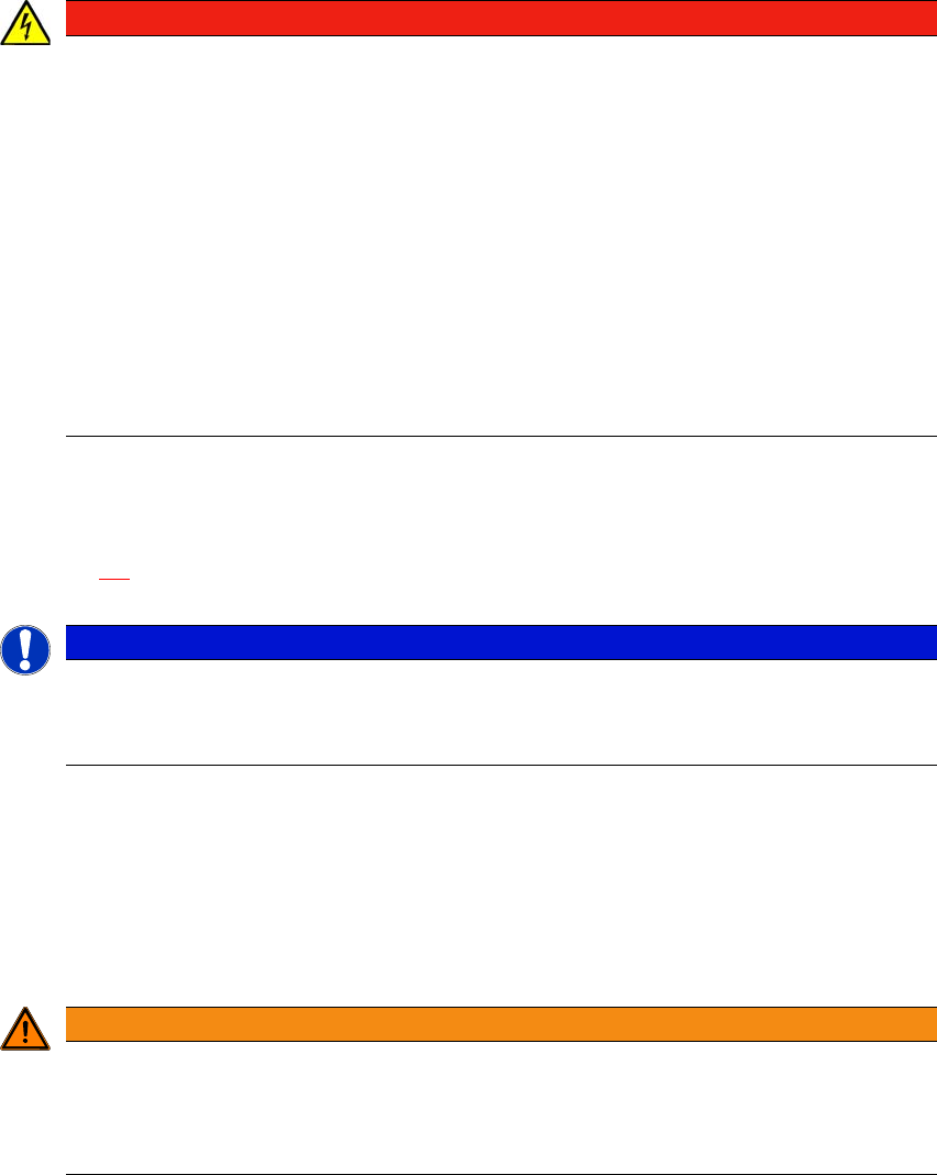
Fig. 4.2 - 3 Description of wires in the mains power cable without Cekon plug
4
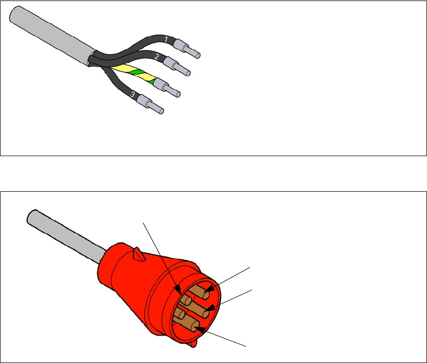
Fig. 4.2 - 4 Assignment in the Cekon plug
1 = (L1): three-phase
2 = (L2): three-phase
3 = (L3): three-phase
green/yellow = (PE): conductor
PE
L1
L2
L3
4 Setting up and commissioning User manual E by SIPLACE
4.2 Infrastructure at the installation location From software version SC 712.1 Edition 05/2019
182
4.2.3.5 Connecting the power supply cable
Crimp a ferrule onto each end of the wire.
Loosen the nuts on the cable fixture.
Run the mains power cable through the cable fixture to the terminal panel X100:1.
Connect L1/L2/L3 to Q1:1 / Q1:3 / Q1:5 respectively. PE connect to terminal block X100:1
Make sure that the bending radius is adequate. The wires must not be kinked.
Manually tighten the cable fixture.
4.2.3.6 Checking the micro-fuses
Low voltages (24 V and 42 V) and the intermediate circuit voltage of the head motors are fused
by micro-fuses.
4
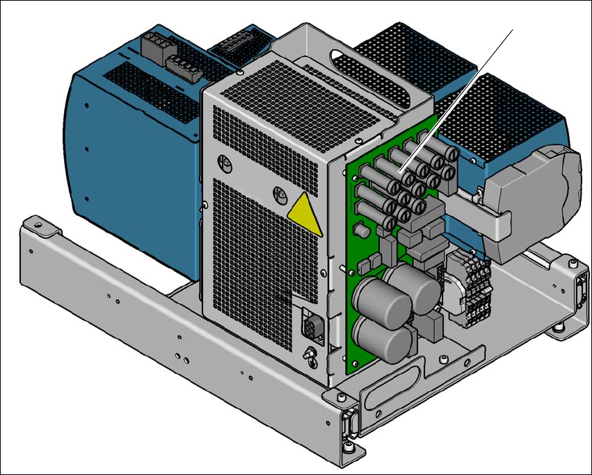
Fig. 4.2 - 5 Micro-fuses on the distribution board of the power supply
(1) Micro-fuses on the distribution board of the power supply
(1)