User Manual E-by-SIPLACE 用户手册.pdf - 第237页
User manual E by SIPLACE 5 Working with the machine From software version SC 712.1 Edition 05/2019 5.11 Setting up t he feeder modules 237 5.11.3.2 Inserting the SIPLACE SmartFeeder E into the changeover table 5 Fig. 5.1…

5 Working with the machine User manual E by SIPLACE
5.11 Setting up the feeder modules From software version SC 712.1 Edition 05/2019
236
Close the pickup window (item 2), by returning the lever (item 3) to its original position.
Remove loose components from the changeover table with a brush or use a vacuum
cleaner with appropriate nozzle.
5
PLEASE NOTE
If the component tape is already inserted, cut it off flush with the front edge of the
feeder module.
User manual E by SIPLACE 5 Working with the machine
From software version SC 712.1 Edition 05/2019 5.11 Setting up the feeder modules
237
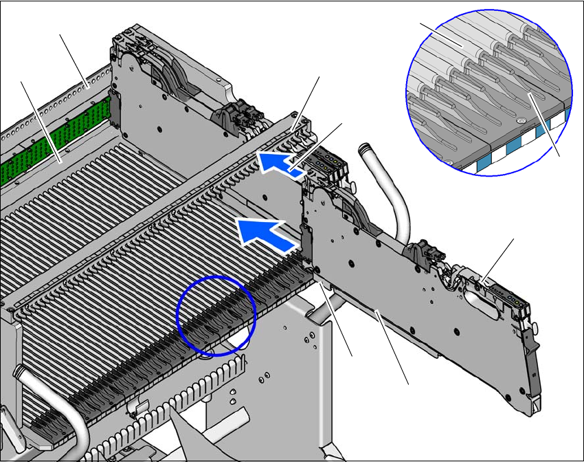
5.11.3.2 Inserting the SIPLACE SmartFeeder E into the changeover table
5
Fig. 5.11 - 3 Inserting the SIPLACE SmartFeeder E into the changeover table
(1) Front slider guide for the feeder module
(2) Back slider guide for the feeder module
(3) Latch on the feeder module
(4) "Front" centering pin on the feeder module
(5) Recesses in the feeder locking bar for latch locking mechanism
(6) Centering bar
(7) Guide profile for the changeover table
(8) Insertion aid for the feeder module
(9) Stop Bar
Place the front slider guide (item 1) of the feeder module on the insertion aid (item 8).
Hold the feeder module vertically and push it forward, along the guide profile (item 7). The
front (item 1) and rear (item 2) slider guides of the feeder module slide on the guide profile
(item 7).
(1)
(2)
(3)
(4)
(5)
(6)
(7)
(8)
(9)
5 Working with the machine User manual E by SIPLACE
5.11 Setting up the feeder modules From software version SC 712.1 Edition 05/2019
238
Carefully push the feeder module further until the "front" centering pin (item 4) is pushed
against the stop bar (item 9).
Check the latch (item 3) of the feeder module as you do so. This must slide easily into the
recess (item 5) in the feeder locking bar, otherwise the feeder module is not seated vertically
on the changeover table or it was not placed on the guide profile (item 7) correctly.
When the feeder module is at the stop position, the locking latch latches onto the locking bar
(item 6) of the feeder table.
5.11.4 Placing the component tape on the SIPLACE SmartFeeder E
5.11.4.1 Checking the feeder module
When you place the component tape in the feeder module, first check whether there are any
components in the vicinity of the pickup window.
Remove any components that you find since they could cause a fault.
5.11.4.2 Preparing the component tape for insertion
Check that there is a straight cut edge at the start of the component tape.
If the transport holes are torn or bent, cut off this part of the tape.
Also make sure that there are no streaks of adhesive on the cover foil.
Pull around 30 cm cover foil away from the component tape if this does not expose any com-
ponents.
Shorten the component tape with the now exposed component pockets by around 3 cm.
Remove the components from the open tape pockets.
Wrap the cover foil around the front edge of the tape along the bottom of the tape.