User Manual E-by-SIPLACE 用户手册.pdf - 第286页
6 Station extensions User manual E by SIPLACE 6.1 Nozzle changer From software version SC 712.1 Edition 05/201 9 286 6 Press the magazine dow n evenly so that th e snap fas tener ba lls engage in all the snap fas - ten…
User manual E by SIPLACE 6 Station extensions
From software version SC 712.1 Edition 05/2019 6.1 Nozzle changer
285
6
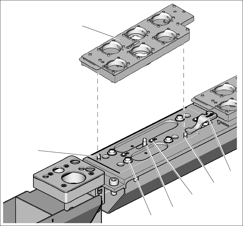
Fig. 6.1 - 20 Nozzle changer for the SIPLACE CP14 - changing the magazine
(1) Lever for raising the magazine
(2) Parallel pin, engages in the hole in the magazine
(3) Spring pin (3 x) for triggering the microswitch
(4) Pin of the slide mechanism, moves the locking plate
(5) Ball of snap fastener
(6) Parallel pin, engages in the slot in the magazine
(7) Magazine
Place the magazine on the snap fastener balls (item 5 in fig. 6.1 - 5, page 262).
(1)
(3)
(4)
(5)
(7)
(6)
(2)

6 Station extensions User manual E by SIPLACE
6.1 Nozzle changer From software version SC 712.1 Edition 05/2019
286
6
Press the magazine down evenly so that the snap fastener balls engage in all the snap fas-
teners at the same time.
PLEASE NOTE
6
Before inserting, align the magazine so that the centering pins (items 2 and 6 in fig.
6.1 - 5, page 262) slide into the centering holes and slot.

User manual E by SIPLACE 6 Station extensions
From software version SC 712.1 Edition 05/2019 6.2 Operator panel (HMI) on location 2
287
6.2 Operator panel (HMI) on location 2
Item no. 03113590Sxx Human-Machine-Interface, loc2
For machines with only one operator panel (HMI) on location 1, you can retrofit an additional HMI
to location 2.
6
Fig. 6.2 - 1 Operator panel (HMI) on location 2
(1) Operator panel (HMI) on location 2
(T) Direction of PCB transport
(1)