User Manual E-by-SIPLACE 用户手册.pdf - 第298页
6 Station extensions User manual E by SIPLACE 6.5 Stationary Cameras From software version SC 712.1 Edition 05 /2019 298 6.5 Stationary Cameras 6.5.1 Stationary component camera, type 25 GigE (FC camera) Item no. 0310520…

User manual E by SIPLACE 6 Station extensions
From software version SC 712.1 Edition 05/2019 6.4 Manual Tray holder E
297
If the tray holder is not present, you can use all 60 feeder tracks on the E by SIPLACE changeover
table or the fixed table. When the E by SIPLACE is a single sided machine, there is a plate (Arbi-
tray Plate E) instead of the changeover table/fixed table that allows a manual tray holder setup.
I
6.4.1 Technical data
6
CAUTION
Avoiding collisions
When moving a changeover table in or out, make sure that the manual tray holder is not
in place as this could cause a collision with the empty tape channel and the nozzle chang-
er holder.
The manual tray holder may only be fitted to the table once the table has been moved
in.
Remove the manual tray holder from the table before moving the table out.
Occupation of locations on the changeover table/fixed table
Manual Tray holder E Speed
Manual Tray holder E Flex
1 to 32
*a
1 to 29
*b
*)a Tracks 33-60 are available for SIPLACE SmartFeeder E docking
*)b Tracks 30-60 are available for SIPLACE SmartFeeder E docking
Configuration in the placement machine
E by SIPLACE Location 2
Placement head range SIPLACE TH, PP, CP14/12/6
Max. waffle pack tray height including components
With SIPLACE TH / SIPLACE PP 25 mm
6 Station extensions User manual E by SIPLACE
6.5 Stationary Cameras From software version SC 712.1 Edition 05/2019
298
6.5 Stationary Cameras
6.5.1 Stationary component camera, type 25 GigE (FC camera)
Item no. 03105205-xx Stationary component camera, type 25 GigE
6
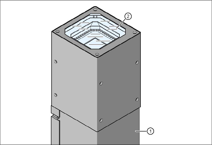
Fig. 6.5 - 1 Stationary component camera, type 25 GigE
(1) Camera housing with integral camera and camera amplifier
(2) Glass plate - illumination and lens levels below

User manual E by SIPLACE 6 Station extensions
From software version SC 712.1 Edition 05/2019 6.5 Stationary Cameras
299
6.5.1.1 Technical data
6
Component dimensions 0.2 mm x 0.2 mm up to 16 mm x 16 mm for single component
measurement
Component range 0402 to SO, PLCC, QFP, sockets, plugs, BGA, special components,
bare dies, flip-chips, shields
Min. lead pitch 0.25 mm
Min. lead width 0.1 mm
Min. ball pitch 0.14 mm
Min. ball diameter 0.08 mm
Field of vision 19.4 mm x 19.4 mm
Illumination type Front-illumination (6 levels, programmable as required)