User Manual E-by-SIPLACE 用户手册.pdf - 第308页
6 Station extensions User manual E by SIPLACE 6.10 External Power Supply COT E From software version SC 712.1 Edition 05/2019 308 6.10 External Power Supply COT E Item no. 00288211-xx Extern al Power Su pply COT E 6 Fig.…
User manual E by SIPLACE 6 Station extensions
From software version SC 712.1 Edition 05/2019 6.9 SIPLACE Power Adapter E
307
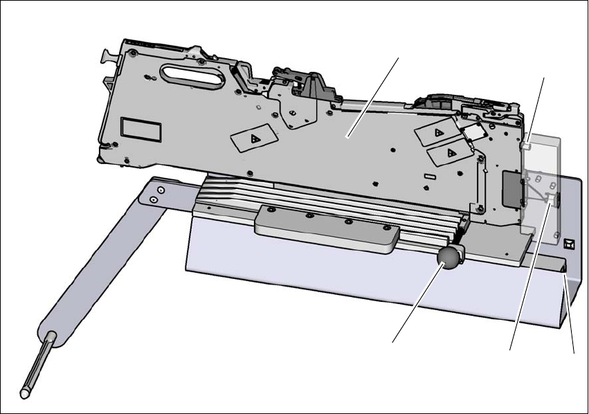
6.9.1 Using the SIPLACE Power Adapter E
Fig. 6.9 - 3 Using the SIPLACE Power Adapter E
Pull the knob (1) when inserting the SIPLACE SmartFeeder E (2) to the SIPLACE Power
Adapter E.
During insertion, ensure the pin (3) on the SIPLACE SmartFeeder E goes into the bushing in
the SIPLACE Power Adapter E. 6
– DC power inlet (4) of the SIPLACE Power Adapter E.
– AC power inlet (5) of the SIPLACE Power Adapter E.
Once the SIPLACE SmartFeeder E sits in place, release the knob to lock the SIPLACE
SmartFeeder E.
To remove the SIPLACE SmartFeeder E from the SIPLACE Power Adapter E, pull the knob
to unlock the SIPLACE SmartFeeder E and remove the SIPLACE SmartFeeder E.
The SIPLACE Power Adapter E comes with 2 power cords for connection to wall outlet. Depend-
ing on the type of wall socket available in your region, please choose the correct power cords.
(3)
(1)
(4)
(5)
(2)
6 Station extensions User manual E by SIPLACE
6.10 External Power Supply COT E From software version SC 712.1 Edition 05/2019
308
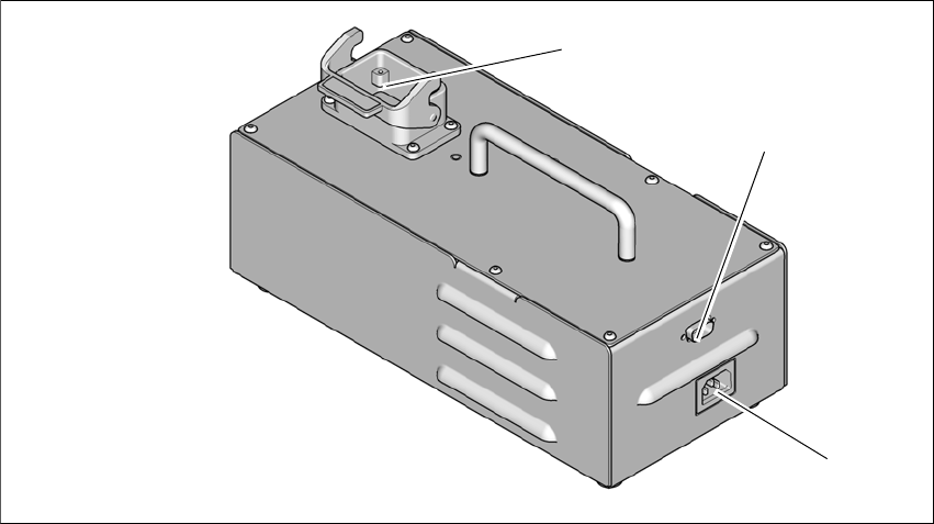
6.10 External Power Supply COT E
Item no. 00288211-xx External Power Supply COT E
6
Fig. 6.10 - 1 External Power Supply COT E
(1) Harting connection
(2) D-sub connection
(3) Power connection
Harting connection
The PowerSupply COT E provides 25V 10A power output to the E series changeover table (COT)
through the Harting connector. Data transfer is also available through this connection, so commu-
nication with the feeders on the changeover table is possible.
D-sub connection
The D-sub connector is used to connect to the Setup Centre through the CAN bus cable. This al-
lows the user to program and setup the feeders on the changeover table at a remote location,
away from the placement machine.
Power connection
The module comes with 2 power cords for connection to wall outlet. Depending on the type of wall
socket available in your region, please choose the correct power cords. The AC inlet accepts a
wide range of voltages and frequencies (100-240 VAC, 50-60 Hz).
After powering on the module, the green LED on the top cover of the module will light up.
(3)
(2)
(1)

User manual E by SIPLACE 6 Station extensions
From software version SC 712.1 Edition 05/2019 6.10 External Power Supply COT E
309
6
PLEASE NOTE
Connection to the SIPLACE Setup Center
Only one External Power Supply COT E with Change over table is to be connected
to SIPLACE Setup Center for feeder setup.
When using the CAN Bus Cable 03040465-xx with SIPLACE Setup Center, the ter-
minal resistor at the bus system end to the SIPLACE Setup Center must be acti-
vated.The terminal resistor at the bus system end to the External PowerS upply COT
E and Change over table must NOT be activated.
The CAN ID for the External Power Supply COT E with Change over table in stand-
alone mode is 0x0518.