User Manual E-by-SIPLACE 用户手册.pdf - 第83页
User manual E by SIPLACE 2 Operational safety From software version SC 712.1 Edition 05/2019 2.7 Safety featur es 83 EMERGENCY STOP button (item 4 in fig. 2.7 - 3 , page 81 and item 3 in fig. 2.7 - 2 , page 80 ) 2 The EM…

2 Operational safety User manual E by SIPLACE
2.7 Safety features From software version SC 712.1 Edition 05/2019
82
Main switch in OFF position (see item 1 in fig. 2.7 - 3, page 81) 2
The main power switch disconnects the three phases L1, L2, and L3 from the power supply.
2
Main switch in ON position 2
After switching on the main switch, mains voltage is present and the 24 V- AC/DC converter is
addressed. The control computer will start up and supply voltage will be made available with the
exception of the intermediate circuit voltages for the gantry axes (300 V-) and star axes (160 V-).
Stop button, black (item 2 in fig. 2.7 - 3, page 81 and item 1 in fig. 2.7 - 2, page 80) 2
This button is used to stop the machine. After reaching STOP state protective lock is released and
covers can be opened.
Start button, white (item 3 in fig. 2.7 - 3, page 81 and item 2 in fig. 2.7 - 2, page 80) 2
After switching on the main power switch you will be prompted to press the start button in order to
start the machine for placement jobs. The same prompt appears if you press the EMERGENCY
STOP button. The protective covers are locked and can no longer be opened.
Component counter 2
The number of placed components (component counter) can be read on the station software. For
more information, refer to the Online Help.
DANGER
Lethal voltages!
Incorrect handling of the machine can therefore result in death or severe injury or consid-
erable damage to equipment.
The following components still carry potentially lethal voltages even if the main power
switch is switched off:
– Cable connection terminals L1, L2, and L3 of the Q1 main power switch
Always follow the applicable accident prevention and DIN regulations (particularly EN
60204, part 1 or IEC 60204, part 1) and the applicable regulations in your own coun-
try.
The safety cover to the power supply must ONLY be opened by appropriately quali-
fied personnel.

User manual E by SIPLACE 2 Operational safety
From software version SC 712.1 Edition 05/2019 2.7 Safety features
83
EMERGENCY STOP button (item 4 in fig. 2.7 - 3, page 81 and item 3 in fig. 2.7 - 2, page 80) 2
The EMERGENCY STOP button is red and latches in the ON position when pressed. When you
press the EMERGENCY STOP button, the switching contact of the EMERGENCY STOP circuit
opens and the safety contactors trips. The link voltage (300 VDC) for the gantry axes and the link
voltage (160 VDC) for the star axes is switched off. The servo amplifiers for the DP and Z axes
are still supplied with 42 VDC. The signaling contact of the EMERGENCY STOP button opens
and the message "EMERGENCY STOP pressed" appears on the screen. The following modules
are deactivated:
– PCB conveyor
– PCB clamping
– Width adjustment
– PCB stopper
– Feeder Control Unit
– Safety valve for the tape cutter
–Star axis
–Gantry axis
2
2
PLEASE NOTE
Placement is interrupted and can then either be continued or canceled once the machine
is working correctly again.
2 Operational safety User manual E by SIPLACE
2.7 Safety features From software version SC 712.1 Edition 05/2019
84
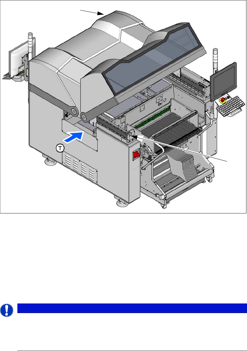
2.7.2.2 Position of protective switches on the machine
2
Fig. 2.7 - 4 Position of protective switches on the machine
(1) Protective cover switch, location 1
(2) Protective cover switch, location 2
Protective cover switch 1 and 2 (item 1 and 2 in fig. 2.7 - 4, page 84) 2
These switches check whether the protective covers are closed. When they are closed, the
EMERGENCY STOP contact and the signaling contact are closed. After pressing the Start button
the covers are locked.
(1)
(2)
PLEASE NOTE
The protective covers are electrically and mechanically locked
During operation, the protective covers are locked and cannot be opened.
Press the stop button. The protective covers can be opened.
See also Section 2.5 on page 71.