User Manual E-by-SIPLACE 用户手册.pdf - 第94页
2 Operational safety User manual E by SIPLACE 2.9 Disabling the compressed air supply and discharging the pre ssure From software version SC 712.1 Edition 05/2019 94 2 Fig. 2.9 - 1 Compressed air unit on the machine (1) …

User manual E by SIPLACE 2 Operational safety
From software version SC 712.1 Edition 05/2019 2.9 Disabling the compressed air supply and discharging the pressure
93
2.9 Disabling the compressed air supply and discharging the
pressure
The compressed air working pressure of the machine is set to 0.50 ± 0.025 MPa (5.0 ± 0.25 bar).
The position of the compressed air unit is shown at item 1 in fig. 2.9 - 1, page 94 ) The supply of
compressed air to the machine can be interrupted with the shutoff valve (item 2 in fig. 2.9 - 1, page
94 ).
Release and open the cover.
Lift the cover (see fig. 2.9 - 1, page 94).
Turn the lever of the shutoff valve (item 5 of fig. 2.9 - 1, page 94) from the vertical to the hor-
izontal position.
Monitor the operating pressure manometer (item 2+3 in fig. 2.9 - 1, page 94 ). When the ma-
chine is switched on, the pressure discharges to 0 MPa (0 bar) within 1 minute.
2
CAUTION
Interruption to compressed air supply!
When the machine is switched on, do not use the stop valve to interrupt the com-
pressed air supply for more than 30 minutes.
If you need to shut off the pneumatic system for longer in order to carry out cleaning
and checking or servicing work, you must switch the machine off at the main switch
and disconnect it from the machine voltage supply.
2 Operational safety User manual E by SIPLACE
2.9 Disabling the compressed air supply and discharging the pressure From software version SC 712.1 Edition 05/2019
94
2
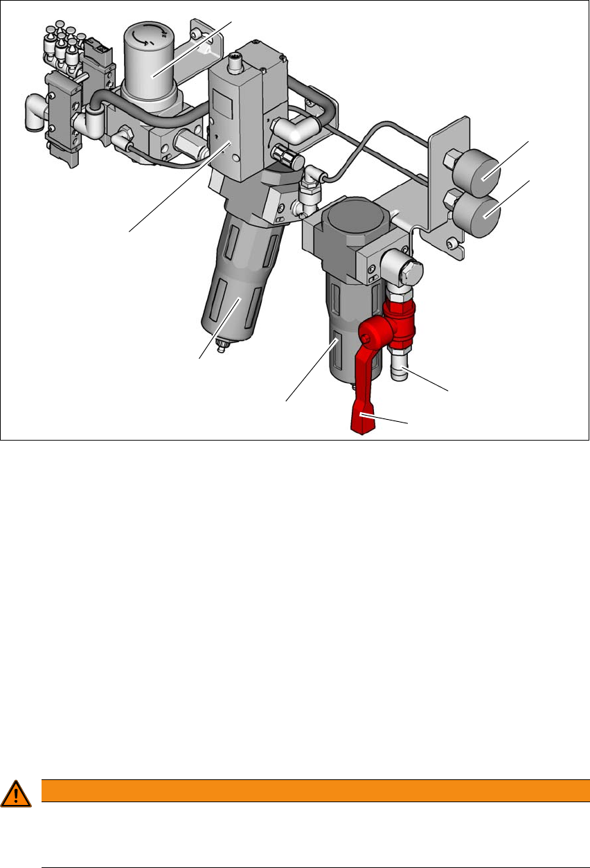
Fig. 2.9 - 1 Compressed air unit on the machine
(1) Regulator for supplying a regulated air source to the tape cutter, nozzle changer and
component table
(2) Manometer for inlet pressure
Target pressure: 0.5 - 1.0 MPa, 5.0 - 10.0 bar (display range: 0 - 1.0 MPa, 0 - 10 bar)
(3) Manometer shows the pressure of the regulator (Pos.1),
Target pressure: 0.45 - 0.5 MPa, 4.5 - 5.0 bar (display range 0 - 0.6 MPa, 0 - 6 bar)
(4) Compressed air connection
(5) Stop valve in the "OPEN" position
(6) Primary fine filter with 5um filter element for achieving output air quality
ISO8573-1:2010 [2:7:3]
(7) Secondary carbon filter for achieving output air quality ISO8573-1:2010 [1:4:1]
(8) Proportional Valve: Input (0.0 - 1.0 MPa, 0-10.0 bar) and output (0.46 - 0.5 MPa, 4.6-5.0 bar)
2
WARNING
Risk of injuries!
Risk of injuries from pressurized compressed air lines.
NEVER detach compressed air lines while they are still pressurized.
(6)
(1)
(2)
(3)
(4)
(5)
(7)
(8)

User manual E by SIPLACE 2 Operational safety
From software version SC 712.1 Edition 05/2019 2.10 Lock out and tag out procedure
95
2.9.1 Compressed air conditions in the machine after switching off at the main power
switch
When you switch off the main switch (item 1 in fig. 2.8 - 1, page 90) or if the mains supply to the
machine fails, the electrically controlled main valve of the compressed air unit (item 1 in fig. 2.9 -
1, page 94 ) will become closed.
2.10 Lock out and tag out procedure
2.10.1 Purpose and scope
Before performing any cleaning and checking work or service work, a procedure of locking and
tagging must be followed. The procedure, when followed correctly eliminates the possibility of an
employee being injured.
2
2.10.2 Description
Whenever it becomes necessary to isolate, control and release energy, the following procedure
is to be followed
Notify affected employees.
Shut down the equipment. Carry out all normal stopping procedures:
– Press the stop button.
– Shut down the control computer.
– Switch the machine off at the main power switch.
Isolate the machine from all its energy sources:
– Shut off the compressed air supply
– Disconnect the mains voltage supply
Lock out the machine.
– Attach a lock whenever possible (e.g. to the main switch).
PLEASE NOTE
Minimum requirements
These procedures represent the minimum lock/tag out requirements for the cleaning and
checking or service work. Any additional safeguards needed to complete work safely can
be specified by facilities supervision, the safety officer, the safety committee and the
health department.