00198382-03_UM_SIPLACE-CA4-V2_EN.pdf - 第296页
7 Station extensions Instruction manual SIPLACE CA4 V2 7.4 Sensor for the component reject bin From software version 71 3.0 Edition 12/2019 296 7.4 Sensor for the component reject bin [001 16848-xx] Query comp onent reje…
Instruction manual SIPLACE CA4 V2 7 Station extensions
From software version 713.0 Edition 12/2019 7.3 SIPLACE Wafer System (SWS)
295
7.3 SIPLACE Wafer System (SWS)
The SIPLACE CA4 V2 facilitates operation with the SIPLACE Wafer System (SWS).
The placement machine can be fitted with an SWS at each location, so that so-called dies can be
placed from wafers. Only the innermost table position is possible at locations 2 and 4. This makes
the components (dies) directly available to the placement head, in wafers. Up to four SIPLACE
Wafer Systems (SWS) can be used at the SIPLACE CA4 V2. The SIPLACE CA4 V2 can also be
operated without an SWS and with four changeover tables at the locations.
To ensure access to the installed SWS in the placement machine, a sliding door has been fitted
to the side of each placement machine location.
See also the user guide for the SIPLACE Wafer Feeder (SWS).
7
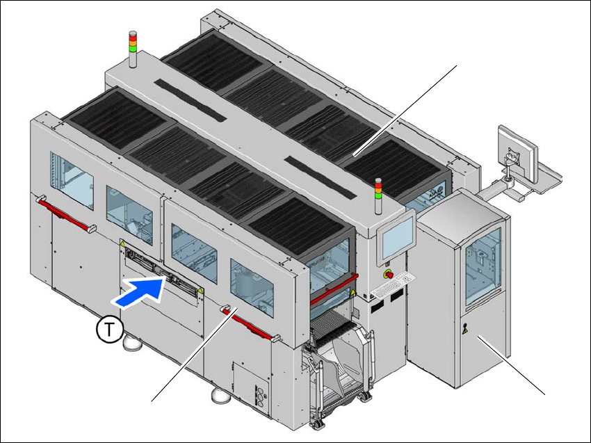
Fig. 7.3 - 1 SIPLACE CA4 V2 placement machine with one SIPLACE Wafer System (SWS)
(1) SIPLACE CA4 V2
(2) SIPLACE Wafer System (SWS) at location 2
(3) Side sliding doors
(T) Direction of PCB conveyor
(1)
(2)
(3)

7 Station extensions Instruction manual SIPLACE CA4 V2
7.4 Sensor for the component reject bin From software version 713.0 Edition 12/2019
296
7.4 Sensor for the component reject bin
[00116848-xx] Query component reject bin X-Series/D3
The sensor for the component reject bin monitors whether the reject bin is seated correctly in its
mount.
– If the reject bin was not inserted correctly, the placement machine cannot be started.
– If the reject bin jumps out of its mount during the placement process, the placement machine
will be stopped immediately to avoid a head crash.
Each reject bin can be monitored by a separate sensor.
7
PLEASE NOTE
When using a SIPLACE SpeedStar (C&P20 M2) at a location without SWS, we recom-
mend that you install the optional sensor for the component reject bin.

Instruction manual SIPLACE CA4 V2 7 Station extensions
From software version 713.0 Edition 12/2019 7.5 PCB barcode scanner
297
7.5 PCB barcode scanner
7.5.1 Description
The PCB barcode reader is used to automatically record and decode barcodes on boards. The
PCB barcode scanners are installed on a special frame on the input side of the placement ma-
chine on the PCB conveyor. Depending on the position of the barcode strips, the barcode scanner
can be attached in a few simple steps so that the strips can be read parallel to or across the PCB
conveyor direction.
When using dual lane conveyors, four board barcode readers can be retrofitted. These can scan
both the top or bottom of the boards on both conveyor lanes.
There are two variants of the barcode scanner:
– 2D board code reader
This code reader processes barcodes and matrix codes. Matrix code is primarily used when
there is
not enough space for barcode labels. 7
7.5.2 Technical data - 2D code reader
7
Dimensions (L x W x H) 55 mm x 42 mm x 22 mm
Weight 125 grams
Code types 2D Data Matrix ECC 0, 50, 80, 100, 140 and 200
Data Matrix ECC200
QR Code, MicroQR Code
Barcode length
Single lane conveyor
Dual lane conveyor, asynchronous
Dual lane conveyor, synchronous
Max. 40 characters
Max. 40 characters
Max. 40 characters
Data interface RS232, USB 2.0
Electrical connection 15-pin D-Sub HD connector
Operating voltage 5 V- to 24 V-