00198382-03_UM_SIPLACE-CA4-V2_EN.pdf - 第112页
3 Technical data and assemblies I nstruction manual SIPLACE CA4 V 2 3.5 Placement head From software version 713.0 Edition 12/2019 112 3.5.2 Overview 3 Fig. 3.5 - 1 SIPLACE SpeedSt ar C&P20 M2 - overview (1) Connecti…

Instruction manual SIPLACE CA4 V2 3 Technical data and assemblies
From software version 713.0 Edition 12/2019 3.5 Placement head
111
3.5 Placement head
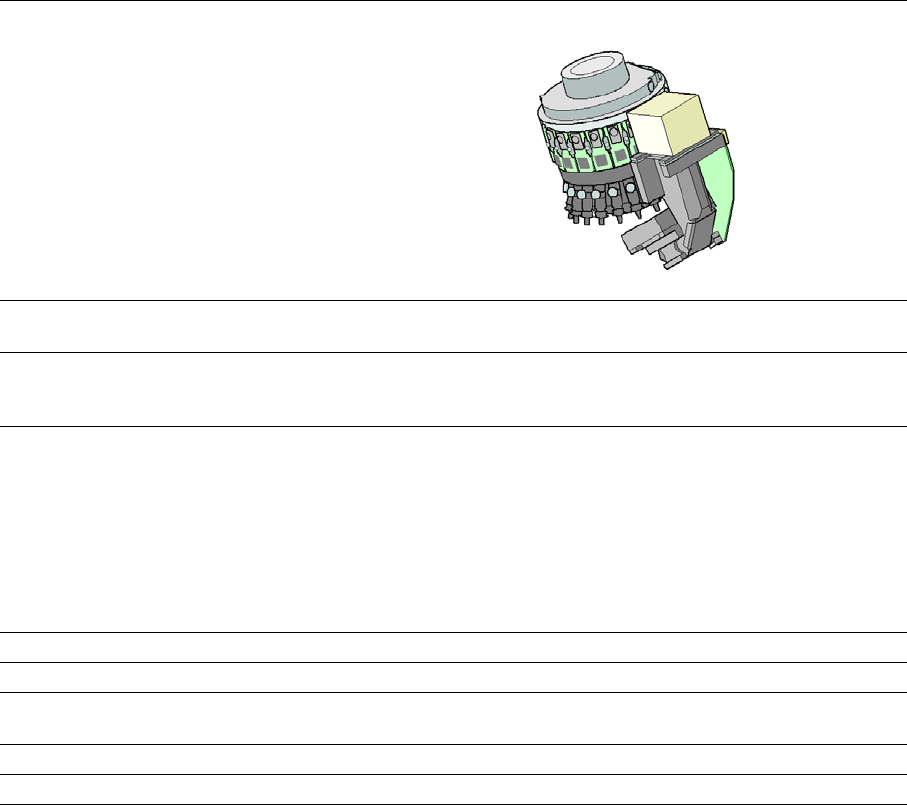
3.5.1 SIPLACE SpeedStar C&P20 M2 for high-precision placement
The SIPLACE SpeedStar C&P20 M is available for top precision placement in the
SIPLACE CA4 V2.
3
CAUTION
Always take hold of the handle to push the placement head
The placement head may only be moved by pushing manually against the handle provid-
ed.
3 Technical data and assemblies Instruction manual SIPLACE CA4 V2
3.5 Placement head From software version 713.0 Edition 12/2019
112
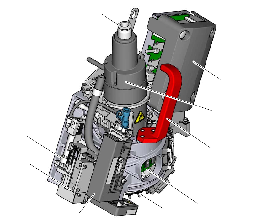
3.5.2 Overview
3
Fig. 3.5 - 1 SIPLACE SpeedStar C&P20 M2 - overview
(1) Connection for the holding circuit of the vacuum pump
(2) "Vacuum sensor holding circuit" board (under the cover)
(3) Star motor
(4) Handle (red)
(5) DP drive
(6) Nozzle
(7) Pressure control valve
(8) Z motor (linear motor)
(9) Return cylinder
(5)
(1)
(7)
(2)
(3)
(4)
(6)
(8)
(9)
Instruction manual SIPLACE CA4 V2 3 Technical data and assemblies
From software version 713.0 Edition 12/2019 3.5 Placement head
113
3.5.2.1 Technical data for SIPLACE SpeedStar (C&P20 M2)
3
SIPLACE SpeedStar (C&P20 M2)
With component camera
type 48
With component camera
type 49
Component range
*a
0.12 mm x 0.12 (0201 metric)
to 2220, Melf, SOT, SOD,
Bare-Die, Flip-Chip
0.12 mm x 0.12 (0201 metric)
to 2220, Melf, SOT, SOD,
Bare-Die, Flip-Chip
Component spec.
Max. height
Min. lead pitch
Min. lead width
Min. ball pitch
Min. ball diameter
Min. dimensions
Max. dimensions
Max. weight
4 mm
70 µm
30 µm
100 µm
50 µm
120 µm x 120 µm
6 mm x 6 mm
1 g
4 mm
*b
50 µm
25 µm
50 µm
25 µm
80 µm x 80 µm
6 mm x 6 mm
1 g
Set-down force Touchless Placement, 0.5 N, 1 N to 4.5 N
Nozzle types 40xx 40xx
X/Y accuracy See also section Placement performance and accuracy on page 95.
Angular accuracy ± 0.2°at 3 ± 0.2°at 3
Illumination level 5 5
*)a Please note that the placeable component range is also affected by the pad geometry, the customer-specific stan-
dards, the component packaging tolerances and the component tolerances.
*)b Due to the focal area of ±0.3 mm, the component camera type 49 requires that you have the correct nozzle length
in relation to the component thickness.