00198382-03_UM_SIPLACE-CA4-V2_EN.pdf - 第121页
Instruction manual SIPLACE CA4 V2 3 Technical data and assemblie s From software version 713.0 Edition 12/2019 3.6 G antry s ystem 121 3.6 Gantry system 3.6.1 Position of gantries SIPLACE CA4 V2 3 Fig. 3.6 - 1 Position o…

3 Technical data and assemblies Instruction manual SIPLACE CA4 V2
3.5 Placement head From software version 713.0 Edition 12/2019
120
3.5.4.5 Technical data for SIPLACE MultiStar (CPP M)
3
SIPLACE MultiStar (CPP M)
With component camera type 45
Component range
*a
*)a Please note that the placeable component range is also affected by the pad geometry, the customer-specific
standards, the component packaging tolerances and the component tolerances.
01005 to 15 mm x 15 mm
*b
*)b Larger components up to 27 mm x 27 mm available on request only
Component spec.
*c
Max. height
Min. lead pitch
Min. lead width
Min. ball pitch
Min. ball diameter
Min. dimensions
Max. dimensions
Max. weight
*)c SIPLACE MultiStar CPP M: in low installation position.
6.0 mm
250 µm / 120 µm
*d
50 µm
140 µm
70 µm
110 µm x 110 µm
15 mm x 15 mm
4 g
*)d Only possible for components which are within the camera focal area of ± 1.3 mm.
Set-down force 1.0 - 10 N
Nozzle types 20xx, 28xx
X/Y accuracy See section Placement performance and accuracy on page 95
Angular accuracy ± 0.1°at 3
Illumination level 5
Instruction manual SIPLACE CA4 V2 3 Technical data and assemblies
From software version 713.0 Edition 12/2019 3.6 Gantry system
121
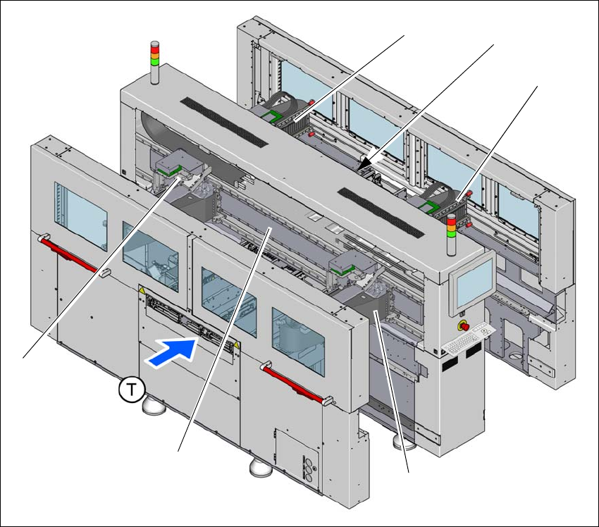
3.6 Gantry system
3.6.1 Position of gantries SIPLACE CA4 V2
3
Fig. 3.6 - 1 Position of gantries - SIPLACE CA4 V2
(1) Y axis, gantry 1 and gantry 4
(2) X axis, gantry 1
(3) X axis, gantry 2
(4) Y axis, gantry 2 and gantry 3 (concealed)
(5) X axis, gantry 3
(6) X axis, gantry 4
(T) Direction of PCB conveyor
(1)
(3)
(6)
(4)
(2)
(5)
3 Technical data and assemblies Instruction manual SIPLACE CA4 V2
3.6 Gantry system From software version 713.0 Edition 12/2019
122
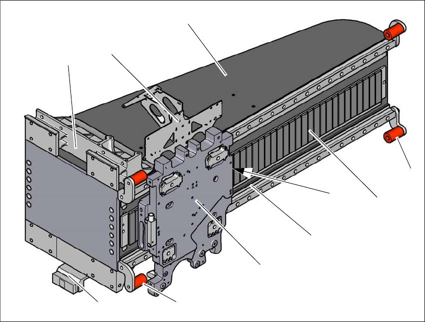
3.6.2 X axis structure
3
Fig. 3.6 - 2 Design of X axis - view of head mount
(1) Head mount with X axis linear motor (primary part)
(2) Y linear motor with fixed bearing (primary part)
(3) Guidance system with permanent magnet (secondary part of the X linear motor)
(4) End position bumper (4x)
(5) Gantry arm
(6) Head board mount
(7) Length measurement system
(8) Sensor module for Y axis
(9) Sensor module for X axis
(4)
(3)
(1)
(5)
(2)
(6)
(4)
(7)
(8)
(9)