00198382-03_UM_SIPLACE-CA4-V2_EN.pdf - 第129页
Instruction manual SIPLACE CA4 V2 3 Technical data and assemblie s From software version 713.0 Ed ition 12/2019 3.7 PCB conveyor syst em 129 3.7.3.5 Synchronous conveyor mod e In synchronous mode, two PCBs of the same si…
3 Technical data and assemblies Instruction manual SIPLACE CA4 V2
3.7 PCB conveyor system From software version 713.0 Edition 12/2019
128
3.7.3.4 Asynchronous conveyor mode
In asynchronous mode, only one PCB in a conveyor lane is processed. At the same time, another
PCB in the second conveyor lane is moved into the placement position. This saves the full con-
veying time of one PCB, thus considerably increasing performance, particularly for PCBs with a
short cycle time. Once the placement machine has received the job data (panel, setup), the
boards on the input conveyors are continuously transported to the available processing conveyor
(provided that the processing conveyor is free) throughout the placement operation. The place-
ment process begins as soon as a board is conveyed into the processing area. The PCBs are pro-
cessed one after another.
If the placement sequence is interrupted, the conveyor interface will be disabled and the PCBs
currently on the processing belts will be completed.
The conveyor interface is disabled or enabled simultaneously for both conveyor lanes.
3
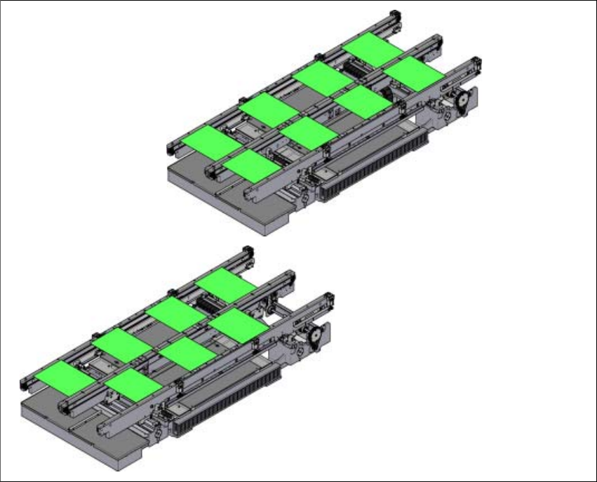
Fig. 3.7 - 4 Conveyor modes
Synchronous conveyor mode
Asynchronous conveyor mode
Instruction manual SIPLACE CA4 V2 3 Technical data and assemblies
From software version 713.0 Edition 12/2019 3.7 PCB conveyor system
129
3.7.3.5 Synchronous conveyor mode
In synchronous mode, two PCBs of the same size are transported into the placement position at
the same time. They are processed as a common panel. When using products with greatly differ-
ing placement content, common optimization increases the performance of the whole content on
both boards.
The time needed to convey the board is reduced as two boards are always conveyed at the same
time. It also ensures better utilization of the nozzle configuration.
PCBs on conveyor lanes 1 and 2 are moved synchronously onto the conveyor sections (i.e. the
conveyors are controlled synchronously, but independently of one another). The components to
be placed on conveyor lanes 1 and 2 must be organized into a panel via two subpanels.
If only one conveyor lane is occupied at the beginning of placement, this single use of the con-
veyor lane will be identified as "not to be placed".
If the dual lane conveyor is operated in synchronous mode, the ‘PCB whispering down the line’
option is deactivated. The "Global bad fiducial" option cannot be used.
3.7.3.6 I-Placement
In addition to synchronous and asynchronous conveyor mode, a new placement concept has
been developed for the SIPLACE CA4 V2: I-Placement. In this mode, the two heads work simul-
taneously and populate a PCB totally independently of one another. This further increases the out-
put.
3 Technical data and assemblies Instruction manual SIPLACE CA4 V2
3.7 PCB conveyor system From software version 713.0 Edition 12/2019
130
3.7.4 Panel lane conveyor
There are two different vacuum tooling options available for the Panel lane conveyor:
– Vacuum tooling L625 x W615 for wide workpiece carriers
– Vacuum tooling L330 x W315 for narrow workpiece carriers
Item no. 00519795-xx Panel lane conveyor vario
Item no. 03152121-xx Vacuum tooling L625 x W615
Item no. 03152135-xx Vacuum tooling L330 x W315
3
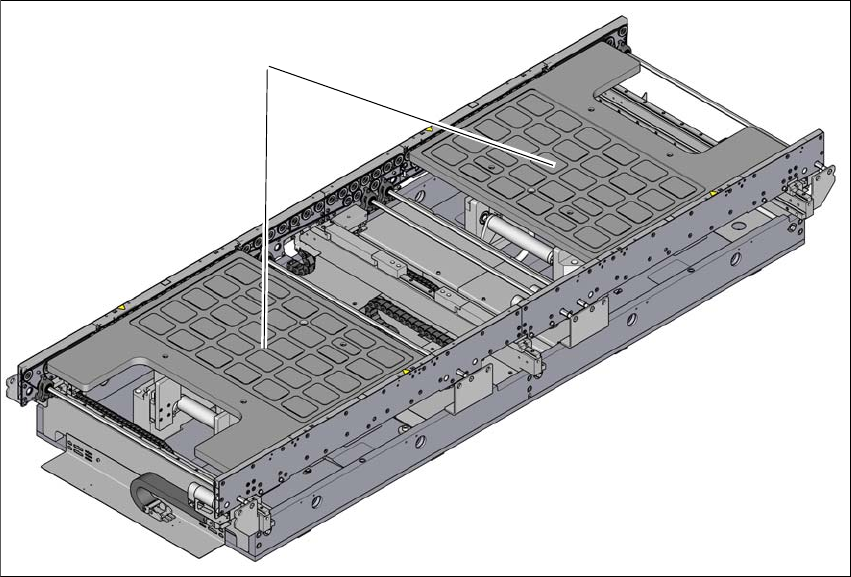
Fig. 3.7 - 5 Panel lane conveyor with vacuum tooling L625 x W615
(1) Vacuum tooling L625 x W615
(1)