00198382-03_UM_SIPLACE-CA4-V2_EN.pdf - 第163页
Instruction manual SIPLACE CA4 V2 4 Setting up and commissioning From software version 713.0 Ed ition 12/2019 4.3 Setting up the pl acement machine 163 4.3 Setting up the placement machine 4.3.1 W arning instructions 4 4…

4 Setting up and commissioning Instruction manual SIPLACE CA4 V2
4.2 Infrastructure at the installation location From software version 713.0 Edition 12/2019
162
4
F5 Distributor power 1 6,3 24
F6 Fan gantry 1 / 4 6,3 24
F7 Fan gantry 2 / 3 6,3 24
F8 Blower Y axis 6,3 24
F9 Trailing 1 6,3 42
F10 Head supply 2 6,3 42
F11 Head supply 3 6,3 42
F12 Head supply 4 6,3 42
F13 Distributor and Vision 6,3 42
F14 Conveyor drives 6,3 42
F15 -- 6,3 27
F16 MCGU 3 6,3 27
F17 MCGU 2 6,3 27
F18 MCGU 1 6,3 27
F19 FCU 4 6,3 27
F20 FCU 3 6,3 27
F21 FCU 2 6,3 27
F22 FCU 1 6,3 27
F23 Head axis 4 6,3 160
F24 Head axis 3 6,3 160
F25 Head axis 2 6,3 160
F26 Head axis 1 6,3 160
PLEASE NOTE
Replacing the microfuses
Only replace the microfuses with approved fuse links!
Fuse Components Electricity
[A]
Voltage [V]
Instruction manual SIPLACE CA4 V2 4 Setting up and commissioning
From software version 713.0 Edition 12/2019 4.3 Setting up the placement machine
163
4.3 Setting up the placement machine
4.3.1 Warning instructions
4
4
4
4
4
WARNING
Observe the applicable accident prevention regulations!
Only SIPLACE engineers or qualified people are permitted to set up and commission the
placement machine.
The applicable accident prevention regulations concerning the transportation of
heavy goods must be followed.
WARNING
Risk of injury during assembly work to the underside of the placement machine!
Risk of injury during assembly work to the underside of the placement machine.
Secure the placement machine using suitable measures. The fork-lift must not be
used as the only support.
WARNING
Risk of injury during assembly work!
Incorrect positioning of gantries during assembly restricts the head clearance and can
lead to injuries.
Take care that the gantries are positioned over the board conveyor area.
WARNING
Setting the height of the placement machine!
Two people will be needed to adjust the height of the placement machine:
– One person completes the required assembly work
– The other person watches the stability of the raised placement machine during
assembly.
WARNING
DANGER OF CRUSHING!
Risk of crushing feet when transporting the placement machine.
Wear specially reinforced shoes.
4 Setting up and commissioning Instruction manual SIPLACE CA4 V2
4.3 Setting up the placement machine From software version 713.0 Edition 12/2019
164
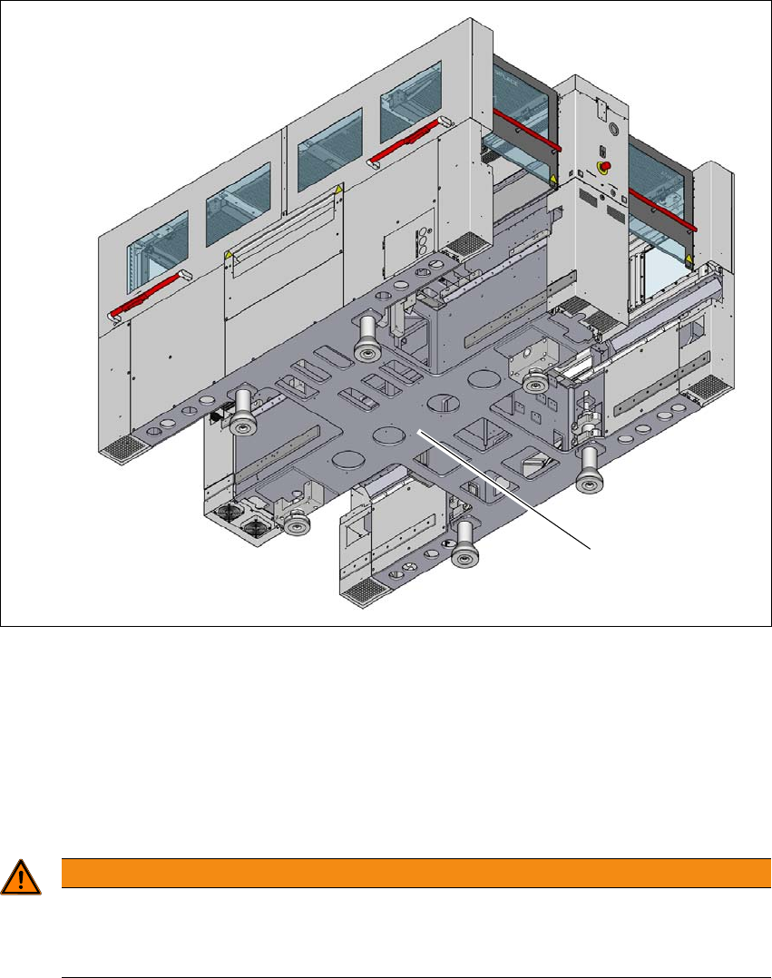
4.3.2 Lifting and transporting the placement machine with the fork lift truck
4
Fig. 4.3 - 1 Contact surfaces - forks parallel to the direction of PCB conveyor
(1) Contact surface for fork lift truck forks
Position the fork-lift truck at right angles to the PCB conveyor and open the forks until the con-
tact surfaces of the placement machine lie evenly on the forks.
Please note the following points before you raise the placement machine in order to avoid irre-
versible damage to the placement machine:
4
WARNING
Aligning the forks
– The forks must be aligned parallel to the PCB conveyor.
– The forks must be aligned parallel to the placement machine.
(1)