00198382-03_UM_SIPLACE-CA4-V2_EN.pdf - 第175页
Instruction manual SIPLACE CA4 V2 4 Setting up and commissioning From software version 713.0 Ed ition 12/2019 4.3 Setting up the pl acement machine 175 Now use the fork-lif t to carefully lower t he p lacement m achine…
4 Setting up and commissioning Instruction manual SIPLACE CA4 V2
4.3 Setting up the placement machine From software version 713.0 Edition 12/2019
174
4
4
4
Carefully loosen both hexagon socket-head screws M24x90 (item 2 in fig. 4.3 - 7, page 173)
with the screwdriver bit (size 19 mm) and let the outer machine foot (item 1 in fig. 4.3 - 7
, page
173
) slowly slide down as far as the end stop.
Insert the correct machine foot for the required PCB conveyor height.
– Outer machine feet for the PCB conveyor heights 900,930 and 950 mm, length
439 mm, Item no. 03000890-02 (item 1 in fig. 4.3 - 4
, page 170 )
Perform this presetting for each of the outer machine feet.
The distance between the machine foot underside and the lower edge of the machine frame
should be as follows:
Adjust the setting screw M24x2x120 (item 3 in fig. 4.3 - 7, page 173) with the fork wrench SW
36, so that you achieve the distance values for the relevant conveyor height, as specified in
the table above.
CAUTION
Risk of cuts at the used tape chute!
When you turn the setting screw M24x2x120 to adjust the height (item 1 in fig. 4.3 - 7
,
page173
) there is a risk of cutting yourself on the sharp edges of the used tape chute.
Always wear thick safety gloves.
WARNING
Heavy machine part
Themachinefeetareveryheavy.Whenlooseningindividualscrews,thesecouldfall
downandcrushlimbs.
When replacing the machine feet, raise the placement machine slightly.
Make sure that no-one is in the hazard area. Risk of crushing due to unintentional
movement or lowering of the placement machine.
WARNING
Do not move the placement machine!
The conveyor sides could be damaged.
Make sure that the placement machine is not moved and that the conveyor sides are
not damaged as a result.
PCB conveyor height Distance of machine foot underside to lower edge of
machine frame
900 mm 190 mm
930 mm 220 mm
950 mm 240 mm

Instruction manual SIPLACE CA4 V2 4 Setting up and commissioning
From software version 713.0 Edition 12/2019 4.3 Setting up the placement machine
175
Now use the fork-lift to carefully lower the placement machine until the machine feet touch
the floor evenly. There should always be a second person present to ensure that the place-
ment machine remains stable while it is being lowered. You may need to loosen the outer ma-
chine feet clamp slightly.
Continue to carefully lower the placement machine, until the outer machine feet touch the
height adjustment setting screws M24x2x120 (item 3 in fig. 4.3 - 7
, page 173).
Make sure that the middle machine feet (see item 2 in fig. 4.3 - 4, page 170) do not yet touch
the ground. If necessary, screw the middle machine feet back into the placement machine or
spacer a little.
4
PLEASE NOTE
For a description of how to perform final adjustment on the placement machine, refer to
the section 4.3.8.1
, page 178.
4 Setting up and commissioning Instruction manual SIPLACE CA4 V2
4.3 Setting up the placement machine From software version 713.0 Edition 12/2019
176
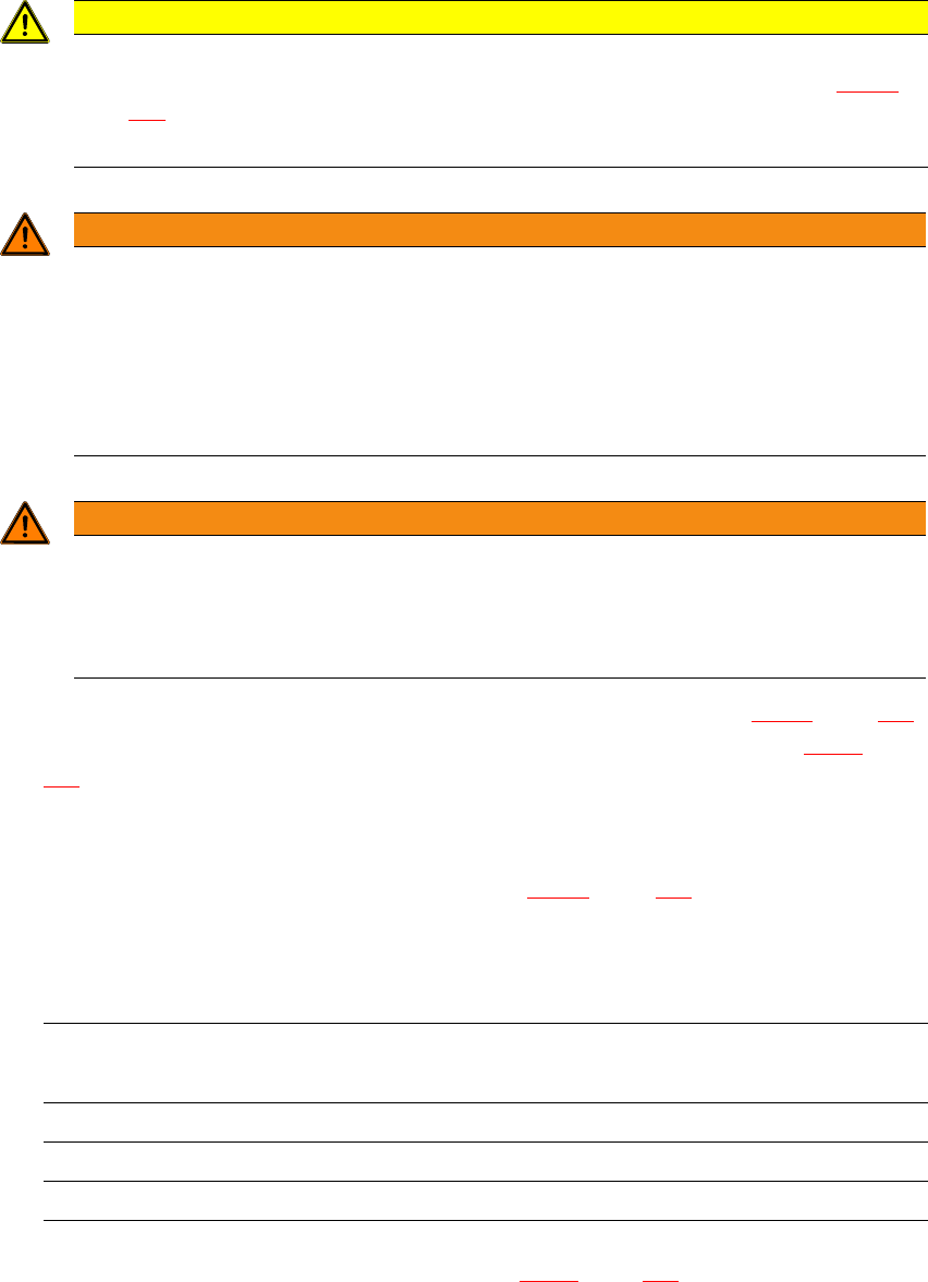
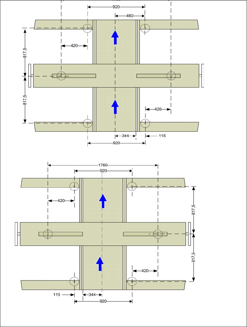
4.3.7 Machine foot clearances and the stationary PCB conveyor edges
Spacing of machine feet for single lane conveyor
4
Fig. 4.3 - 8 Spacing of machine feet for single lane conveyor in millimeters
Fixed conveyor side at maximum
right position
a
.
a) The value depends on the position of the fixed side. All dimensions in millimeters.
Fixed conveyor side at maximum
left position
a
.