00198382-03_UM_SIPLACE-CA4-V2_EN.pdf - 第184页
4 Setting up and commissioning Instruction manual SIPLACE CA4 V2 4.3 Setting up the placement mac hine From software versio n 713.0 Edition 12/2019 184 4 4 CAUTION Reduced product life of b earings and guide rails! If th…
Instruction manual SIPLACE CA4 V2 4 Setting up and commissioning
From software version 713.0 Edition 12/2019 4.3 Setting up the placement machine
183
4.3.8.3 Fitting the floor brace (optional)
The placement machine can be secured against sliding in the event of strong vibrations (e.g.
earthquakes) with a floor brace, if required.
Fit a floor brace to each machine foot.
4
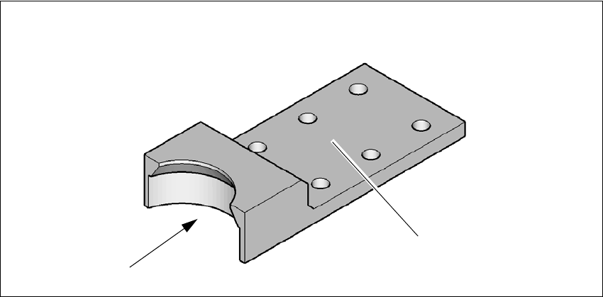
Fig. 4.3 - 14 Floor brace
Place the floor brace (1) over the machine foot.
Attach the floor brace to the floor with suitable fixtures, at the six holes (2) provided.
4.3.9 Removing the shipping braces
The shipping braces are attached to the linear guides. Each gantry is fastened with two shipping
braces on the X and Y axes.
Remove all the shipping braces from the gantry axes.
If the SIPLACE placement machine needs to be transported, always fit the shipping braces
back onto the conveyor.
4.3.10 Removing the corrosion protection from the guide rails
The placement machines were given a corrosion protection treatment before they were delivered.
(2)
(1)
4 Setting up and commissioning Instruction manual SIPLACE CA4 V2
4.3 Setting up the placement machine From software version 713.0 Edition 12/2019
184
4
4
CAUTION
Reduced product life of bearings and guide rails!
If the corrosion protection agent is mixed with the bearing grease on the axes this can
greatly reduce the service life of the bearings and guide rails.
You should therefore remove the corrosion protection from all the axes and bearings
when you traverse the machine axes for the first time during commissioning.
Grease all the axes and bearings with the grease described in the maintenance in-
structions.
CAUTION
Risk of damaging bearing grease!
Alcohol will damage the bearing grease in the guide carriages.
When cleaning the guide rails and scales, make sure that alcohol does not get into
the guide trolley.
Instruction manual SIPLACE CA4 V2 4 Setting up and commissioning
From software version 713.0 Edition 12/2019 4.4 Adjusting the component trolley to the PCB conveyor height
185
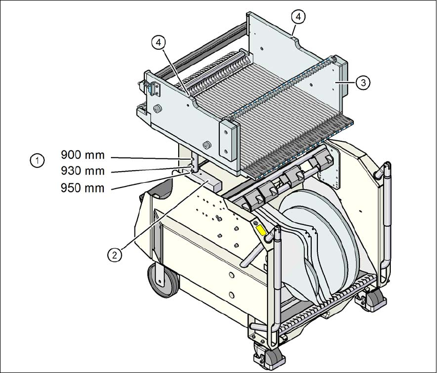
4.4 Adjusting the component trolley to the PCB conveyor
height
The component trolley can be easily and quickly adjusted to the following PCB conveyor heights:
900 mm 4
930 mm (standard height) 4
950 mm (SMEMA height) 4
4
Fig. 4.4 - 1 Component trolley
(1) Holes for the conveyor heights of 900, 930 and 950 mm.
(2) Block
(3) Changeover table
(4) M8 holes for fixing the mounting device