00198382-03_UM_SIPLACE-CA4-V2_EN.pdf - 第207页
Instruction manual SIPLACE CA4 V 2 5 Tasks at the placement machi ne From software version 713.0 Ed ition 12/2019 5.5 The user interfac e 207 5.5.4 Operating the st ation sof tware in the views Most views which can be ac…
5 Tasks at the placement machine Instruction manual SIPLACE CA4 V2
5.5 The user interface From software version 713.0 Edition 12/2019
206
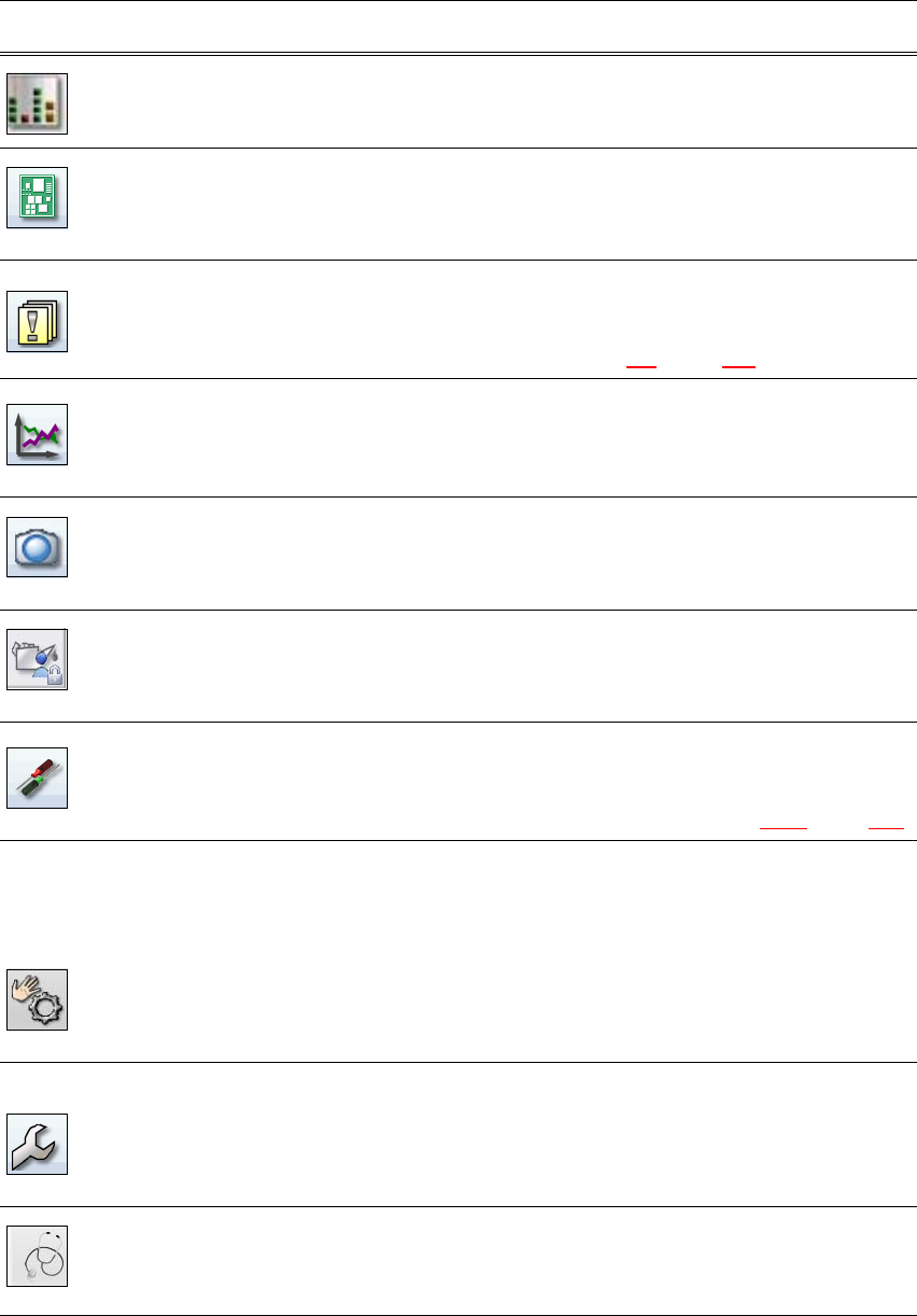
Filling level view During placement, the operator is shown at all times when the
individual feeders will run empty and need to be filled up again.
PCBs Shows the boards and placement positions list.
Allows you to check and configure boards and components.
Allows you to teach fiducials.
Notifications Shows notifications about current and previous events. The notifi-
cations vary according to their type. Individual tables can be viewed
for track errors, conveyor errors, machine errors, general errors and
linked error messages (see section 5.6
, page 211).
Statistics Shows the statistics for performance, quality and rejected material.
Shows the machine and board performance.
Starts the OIS (Operator Information System), for more information
refer to the OIS documentation.
Live image during
placement
Shows the individual live camera images.
Only available from operator level "Advanced Production" :
Allows you to view and save the Vision dump.
Maintenance sta-
tus
Contains information about the maintenance status for the place-
ment machine.
Refer to the maintenance guide for further information.
Settings Contains all the settings and options.
Allows you to set the operator level and the user interface language.
Allows you to display and edit the machine settings, user settings,
machine options and software options, see section 5.5.5
, page 209.
Check sensors
and functions
Contains information and functions for tests and diagnoses.
Allows you to set the function of the start button for the placement
machine.
Only available from operator level "Advanced Production" :
Allows you to test the complete reference run and C&P20 head
functions.
Single functions and continuous runs. Each gantry is addressed
individually.
Service Service tools.
Only available from operator level "Service (customer)".
Allows you to set up and calibrate the SIPLACE placement ma-
chines, download embedded software versions, calibrate and con-
figure the entire machine.
Test bench in-
spection
Only available in the operator level Machine service.
For a detailed description of the individual functions refer to the
Online Help.
Icon View Description
Instruction manual SIPLACE CA4 V2 5 Tasks at the placement machine
From software version 713.0 Edition 12/2019 5.5 The user interface
207
5.5.4 Operating the station software in the views
Most views which can be accessed via the toolbar (see section 5.5.3, page 205) have an addi-
tional vertical toolbar with subviews and functions, on the right-hand side of the user interface.
5
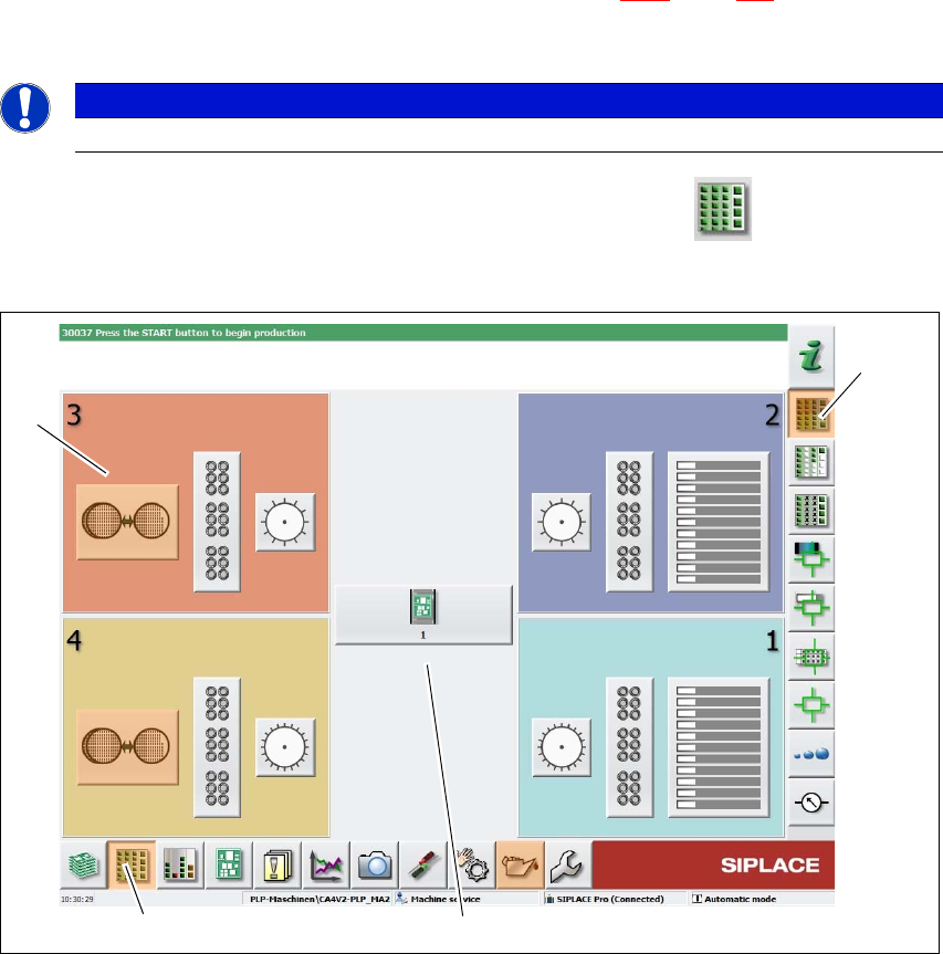
Example: View: "Feeder modules, components and nozzles"
Click on "Feeder modules, components and nozzles" in the toolbar.
The following view will open:
5
Fig. 5.5 - 3 User interface in the "Feeder module, components and nozzles" view (example)
Legend
(1) Toolbar ("Feeder modules, components and nozzles" button)
(2) Vertical toolbar in "Feeder modules, components and nozzles" view
(3) Processing area with 4 gantries
(4) Button for SIPLACE Wafer System (SWS) at location 3
Click, for example, on the SIPLACE Wafer System (SWS) (4) to open the SWS functions.
PLEASE NOTE
For a detailed description of the individual functions refer to the Online Help.
(1)
(2)
(3)
(4)
5 Tasks at the placement machine Instruction manual SIPLACE CA4 V2
5.5 The user interface From software version 713.0 Edition 12/2019
208
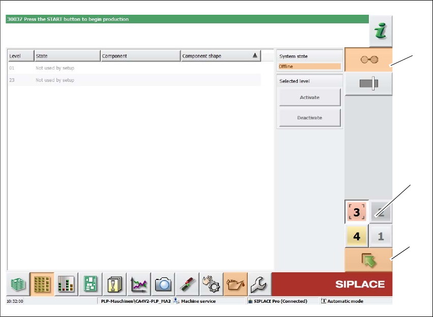
The following view will open:
5
Fig. 5.5 - 4 User interface in the "SIPLACE Wafer System" (example) view
Legend
(1) Vertical toolbar for "SIPLACE Wafer System" functions
(2) Buttons for changing directly to a different gantry
(3) "Up one level" button, to return to previous view (here: "Feeder modules, components and
nozzles" view, see previous diagram)
(1)
(3)
(2)