00198382-03_UM_SIPLACE-CA4-V2_EN.pdf - 第220页
5 Tasks at the placement machine Instruction manual SIPLACE CA4 V2 5.8 Shift changeover From software version 713.0 Edition 12/2019 220 5.8 Shif t changeover 5.8.1 Shif t changeover tasks S plice the tape s early . The…
Instruction manual SIPLACE CA4 V2 5 Tasks at the placement machine
From software version 713.0 Edition 12/2019 5.7 Indicator lamps with horn
219
5.7.2 Customized configuration of indicator lamp
Click on "Settings" in the toolbar of the station software .
Click on "User" .
Go to Customized configuration of indicator lamp and click on Configure...
–The Lamp configuration tool will start.
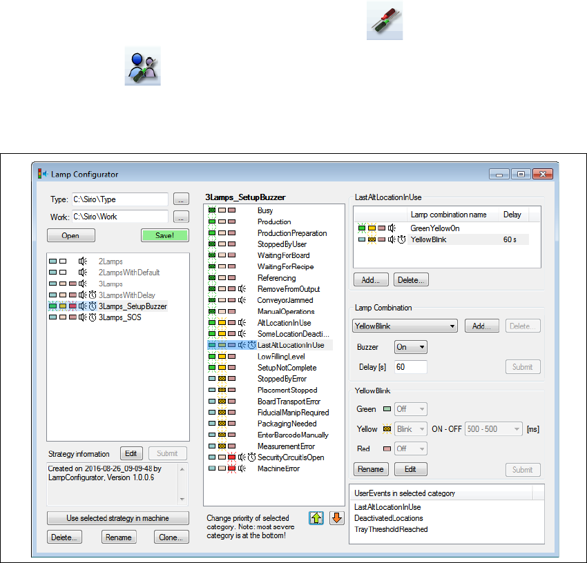
Fig. 5.7 - 4 Lamp configuration tool
This tool is used to adjust the indicator lamp settings to your application case. Both the lamps and
the buzzer signals can be individually configured.
Restart the machine after changing the settings, so that the new configuration is enabled.
If the settings are not only to be used on the current placement machine, you will need to distribute
the configuration via the programming system
Go to Customized configuration of indicator lamp and click on Distribute...
The indicator lamp settings valid on this placement machine will be sent to the programming sys-
tem and from there transferred to all placement machines in this line. These settings will then be
valid for all placement machines with the same indicator lamp configuration.

5 Tasks at the placement machine Instruction manual SIPLACE CA4 V2
5.8 Shift changeover From software version 713.0 Edition 12/2019
220
5.8 Shift changeover
5.8.1 Shift changeover tasks
Splice the tapes early. The feeder modules do not have to be refilled as soon as the new shift
starts. This minimizes extended down times.
At the shift change, pass important information on to the next operator. This includes, for in-
stance, changes to the placement program. Also read through the list of the descriptions of
the steps to take in section 5
, page 193.
Carry out a setup check.
Make sure that the feeder modules are equipped with the correct components, that they are
at the correct locations in the component trolley and that the conveyor increment is set cor-
rectly.
Clean the following line assemblies:
Empty the placement machine reject bin and carefully vacuum the area around the reject bin.
Empty the SWS reject bin and carefully vacuum the area around the reject bin.
Carefully vacuum the nozzle changer, feeder modules and the component trolley.
Empty the waste tape container. Follow the safety instructions given in section 5.8.2, page
221
.
Instruction manual SIPLACE CA4 V2 5 Tasks at the placement machine
From software version 713.0 Edition 12/2019 5.8 Shift changeover
221
5.8.2 Safety instructions for emptying the waste tape container
5
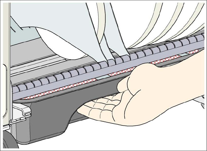
Fig. 5.8 - 1 Safety instructions for emptying the waste tape container
The waste tape container must be pulled out of the component trolley for emptying. There is a risk
of catching your thumbs as you do so.
To avoid this risk, take hold of the underside of the grab recess on the waste tape container
with your fingers and place your thumbs on top of the grab recess.
Do NOT put your thumbs in the gap between the tape container and waste tape container as
you could trap your thumbs if you do.