00198382-03_UM_SIPLACE-CA4-V2_EN.pdf - 第225页
Instruction manual SIPLACE CA4 V 2 5 Tasks at the placement machi ne From software version 713.0 Edition 12/2019 5.9 Carrying out a si ght check 225 5.9.5 Inserting sep arating p lates into the t ape container The sepa…
5 Tasks at the placement machine Instruction manual SIPLACE CA4 V2
5.9 Carrying out a sight check From software version 713.0 Edition 12/2019
224
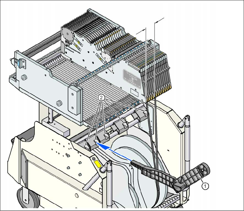
5.9.4 Mount of additional tape reel
5
Fig. 5.9 - 2 Mount of additional tape reel
(1) Mount of additional tape reel, item no. 00141217-xx
(2) Mounting device for the support
5
X-Series S feeder modules can process component tapes without problems if the lateral offset be-
tween the feeder module and the tape reel does not exceed 60 mm.
If a predefined setup means that the maximum permitted offset cannot be maintained, we recom-
mend that you use the mount for an additional tape reel (item 1). Simply insert the mount into the
holder (item 2) and push it until the offset is less than the maximum permitted value of 60 mm. The
component trolley has 5 holders in total. Each tape reel mount can hold 2 tape reels, which means
that up to ten 15" (381 mm) reels can be positioned above the tape container.
Max. 60 mm
Instruction manual SIPLACE CA4 V2 5 Tasks at the placement machine
From software version 713.0 Edition 12/2019 5.9 Carrying out a sight check
225
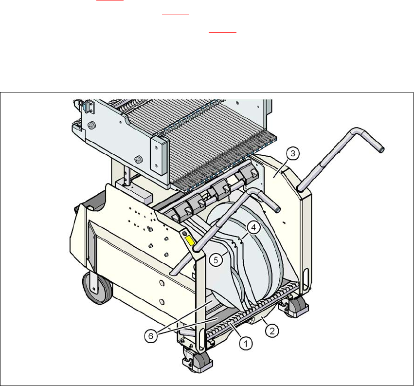
5.9.5 Inserting separating plates into the tape container
The separating plate has different edges and can be inserted into the tape container in two
ways. If spindles are used, the recesses for the spindles in the separating plate point upwards
(see item 4 in fig. 5.9 - 3
). If you do not use spindles, the rounded edge of the separating
plate points up (see item 5 in fig. 5.9 - 3
).
Insert the separating plates as shown in fig. 5.9 - 3 and remember that the smallest division
of the tape container is a 2x division. This will help avoid placement errors.
Check that the separating plates engage in the same positions on the three guide rails. Oth-
erwise the separating plate will be offset or bent.
5
Fig. 5.9 - 3 Separating plates in the tape container
(1) Guide rail for the separating plates
(2) Waste tape container
(3) Tape container
(4) Position of the separating plate if spindles are used
(5) Position of the separating plate if no spindles are used
(6) Sliding support for tape reels
5 Tasks at the placement machine Instruction manual SIPLACE CA4 V2
5.10 Setting up the feeder modules From software version 713.0 Edition 12/2019
226
5.10 Setting up the feeder modules
5.10.1 Notes on handling feeder modules
Feeder modules are precision devices. You should therefore handle the feeder modules with care.
Avoid bumping feeder modules into obstacles.
Do not drop the feeder modules.
Always use suitable tools for preventive maintenance.
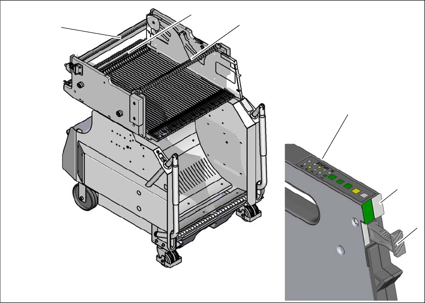
5.10.2 Removing X feeder modules from the changeover table
5
Fig. 5.10 - 1 Removing X feeder modules from the changeover table
(1) Removal handle
(2) Status display
(3) LED display
(4) Rail for checking height of feeder
(5) Latch for locking the feeder modules
(6) Centering rail
5
(2)
(1)
(4)
(5)
(6)
(3)