00198382-03_UM_SIPLACE-CA4-V2_EN.pdf - 第237页
Instruction manual SIPLACE CA4 V 2 5 Tasks at the placement machi ne From software version 713.0 Ed ition 12/2019 5.11 Observing displa ys on the feeder module 237 5.1 1.2 St atus display –G r e e n : The feeder module i…
5 Tasks at the placement machine Instruction manual SIPLACE CA4 V2
5.11 Observing displays on the feeder module From software version 713.0 Edition 12/2019
236
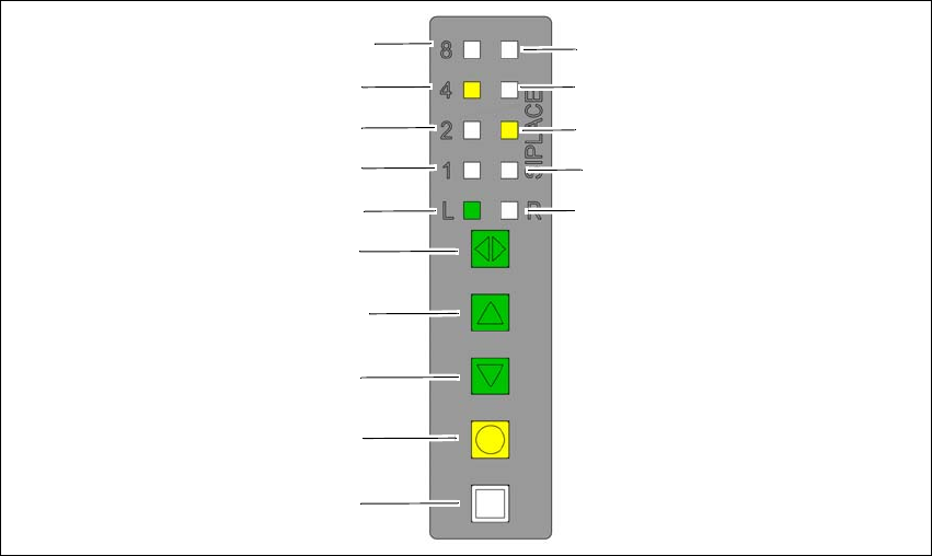
5.11.1 Operating panel - LED display
The SIPLACE SmartFeeder have a multicolored status display for each track and LED displays,
to indicate the operating states.
5
Fig. 5.11 - 2 Buttons, LED and status displays: Example of SIPLACE SmartFeeder 2x8 mm
(1) SET button
(2) FOIL button
(3) BACK button
(4) FORWARD button
(5) Track change button for switching between right and left
(6) LED L left track active
(7) LED 1 mm increment for left track
(8) LED 2 mm increment for left track
(9) LED 4 mm increment for left track
(10) LED 8 mm increment for left track
(11) LED R right track active
(12) LED 1 mm increment for right track
(13) LED 2 mm increment for right track
(14) LED 4 mm increment for right track
(15) LED 8 mm increment for right track
(8)
(1)
(2)
(3)
(4)
(5)
(6)
(7)
(9)
(10)
(15)
(14)
(13)
(12)
(11)

Instruction manual SIPLACE CA4 V2 5 Tasks at the placement machine
From software version 713.0 Edition 12/2019 5.11 Observing displays on the feeder module
237
5.11.2 Status display
–Green:
The feeder module is on standby and is contained in the current setup.
– Orange:
A warning is being signalized.
–Red:
A malfunction has occurred.
–Off:
The feeder module is not in the current setup.
5
5
5
PLEASE NOTE
"LED off" only for feeder modules contained in the setup
The placement machine controller switches off the status display of any feeder modules
not included in the setup.
The "LED off" status only occurs when the programming system has preset a job on the
line. This takes some of the work away from the operator since he only has to watch
those feeder modules that are contained in the setup.
PLEASE NOTE
Setup procedure: Activation of LED for each feeder module
For the actual setup process - no setup information at the station, no job sent from SI-
PLACE Pro to the station/line - the LED on each feeder module is activated after the set-
up has been made. The operator is thus informed whether everything is OK.
5 Tasks at the placement machine Instruction manual SIPLACE CA4 V2
5.12 Changing the setup From software version 713.0 Edition 12/2019
238
5.12 Changing the setup
5.12.1 Changing the setup on the placement machine
5.12.1.1 Printing out the conversion instructions before changing the setup
Before a change of setup, print out the conversion instructions on the printer for the SIPLACE Pro
computer as described in the "SIPLACE Pro" manual or in the Online Help.
5.12.1.2 What you should note when changing the feeder modules
Handle the feeder modules carefully when you insert them into or remove them from the
changeover table. Make sure that the X feeder modules do not bump against the centering
bar (see item 5 in fig. 5.10 - 3
, page 230) of the changeover table.
Vacuum the supporting surfaces of the feeder modules and clean the surface of the table
when necessary according to the instructions in the preventive maintenance manual.
Remove loose components using a brush or a vacuum cleaner with a suitable nozzle.
5
CAUTION
Risk of injuries!
Fine metal splinters from components could injure hands.
Avoid removing components from the changeover table with your fingers.