00198382-03_UM_SIPLACE-CA4-V2_EN.pdf - 第292页
7 Station extensions Instruction manual SIPLACE CA4 V2 7.1 Nozzle changer From software version 713.0 Edition 12/2019 292 Place the magazine on the snap fa stener balls (item 5 in fig. 7.1 - 9 , pag e 291 ). Press th…
Instruction manual SIPLACE CA4 V2 7 Station extensions
From software version 713.0 Edition 12/2019 7.1 Nozzle changer
291
7
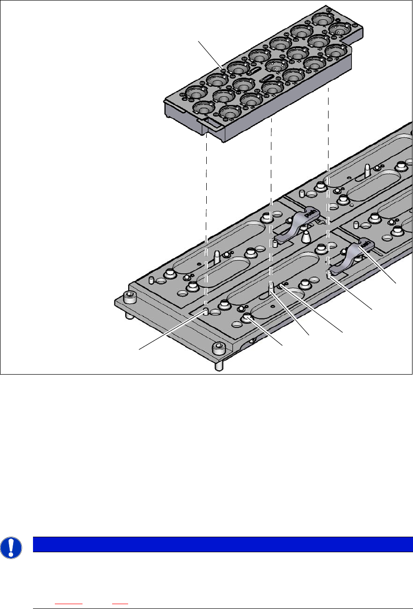
Fig. 7.1 - 9 Nozzle changer for the C&P/CPP - changing the magazine
(1) Lever for raising the magazine
(2) Parallel pin, engages in the hole in the magazine
(3) Spring pin for triggering the microswitch
(4) Pin of the slide mechanism, moves the locking plate
(5) Ball of snap fastener
(6) Parallel pin, engages in the slot in the magazine
(7) Locking plate in the "magazine locked" position
7
PLEASE NOTE
7
Move the locking plate into the "Magazine locked" position.
Before inserting, align the magazine so that the centering pins (items 2 and 6 in fig.
7.1 - 9
, page 291) can slide into the centering holes and slot.
(1)
(2)
(3)
(4)
(5)
(6)
(7)
7 Station extensions Instruction manual SIPLACE CA4 V2
7.1 Nozzle changer From software version 713.0 Edition 12/2019
292
Place the magazine on the snap fastener balls (item 5 in fig. 7.1 - 9, page 291).
Press the magazine down evenly so that the snap fastener balls engage in all the snap fas-
teners at the same time.
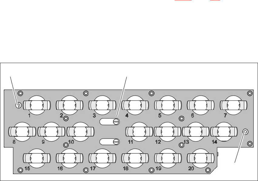
7.1.3.3 Position detection
Each nozzle changer magazine has two fiducials for determining the position.
7
Fig. 7.1 - 10 Nozzle magazine - holder numbering, fiducials for determining the position and angular position
(1) Locking plate in the "magazine open" position
(2) Fiducials for determining the position
(1)
(2)
(2)
Instruction manual SIPLACE CA4 V2 7 Station extensions
From software version 713.0 Edition 12/2019 7.2 Vacuum pump
293
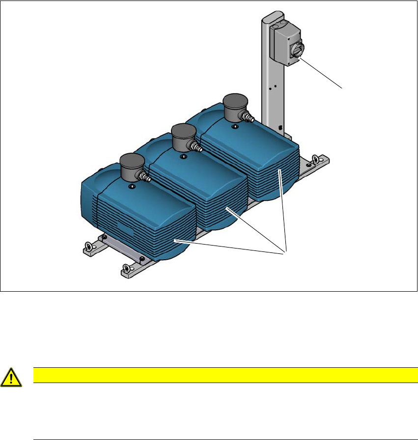
7.2 Vacuum pump
The vacuum pumps for the head supply and vacuum tooling (if present) are located on a frame
next to the placement machine. This frame is also used as an earthquake anchor and can be
screwed into the ground. The vacuum pumps for the heads are controlled by the placement ma-
chine and can only be switched off via the placement machine. The vacuum tooling vacuum pump
has its own switch and bypass valve.
7.2.1 Overview
7
Fig. 7.2 - 1 Overview - vacuum pumps on rack
(1) Vacuum pumps (2x head supply and 1x vacuum tooling)
(2) Switch for the vacuum tooling vacuum pump
7
7
CAUTION
Vacuum pumps next to the placement machine
If the vacuum pumps are next to the placement machine or outside the placement ma-
chine installation location (clean room operation), the customer will need to perform a
hazard assessment and make sure that the operation of these pumps is safe.
(1)
(2)