00198382-03_UM_SIPLACE-CA4-V2_EN.pdf - 第61页
Instruction manual SIPLACE CA4 V2 2 Operational safety From software version 713.0 Edition 12/2019 2.3 Classification of camera systems 61 2.3.2 Classification of the camera systems 2.3.2.1 Camera types with bright LEDs …
2 Operational safety Instruction manual SIPLACE CA4 V2
2.3 Classification of camera systems From software version 713.0 Edition 12/2019
60
2.3 Classification of camera systems
2.3.1 Classification of the whole machine
2
2.3.1.1 Laser classification
The following modules are assigned to risk class 2:
2
The ready-for-operation placement machine is assigned to risk class 2.
The risk classes are determined according to IEC 60825-1:2014.
Assembly Data
Component sensor on SpeedStar Maximum optical output power: < 1 mW
Wavelength: 635 nm
Component sensor on the SIPLACE Multis-
tar CPP
Maximum optical output power: < 1 mW
Wavelength: 635 nm
Laser light barrier on PCB conveyor Maximum optical output power: < 1 mW
Wavelength: 650 nm
Instruction manual SIPLACE CA4 V2 2 Operational safety
From software version 713.0 Edition 12/2019 2.3 Classification of camera systems
61
2.3.2 Classification of the camera systems
2.3.2.1 Camera types with bright LEDs - risk group 1
The bright LEDs are fitted in the following cameras. These are classified as risk group 1, according
to IEC 62741:.
– Component camera type 45 and 49
– PCB camera, type 28
2
2.3.2.2 Camera types with blue LEDs - risk group 2
The ultra-bright blue LEDs are fitted in the following cameras. These are classified as risk group
2, according to IEC 62741:.
– Component camera, type 48
2
2
PLEASE NOTE
Risk group 1
Do not look into the beam of the ready-for-operation camera!
2
Risk group 2
The beam from cameras with ultra-bright blue LEDs can be a haz-
ard.
Do not look into the beam of the ready-for-operation camera!
2 Operational safety Instruction manual SIPLACE CA4 V2
2.4 Safety instructions for transportation From software version 713.0 Edition 12/2019
62
2.4 Safety instructions for transportation
2.4.1 Transporting the placement machine
2
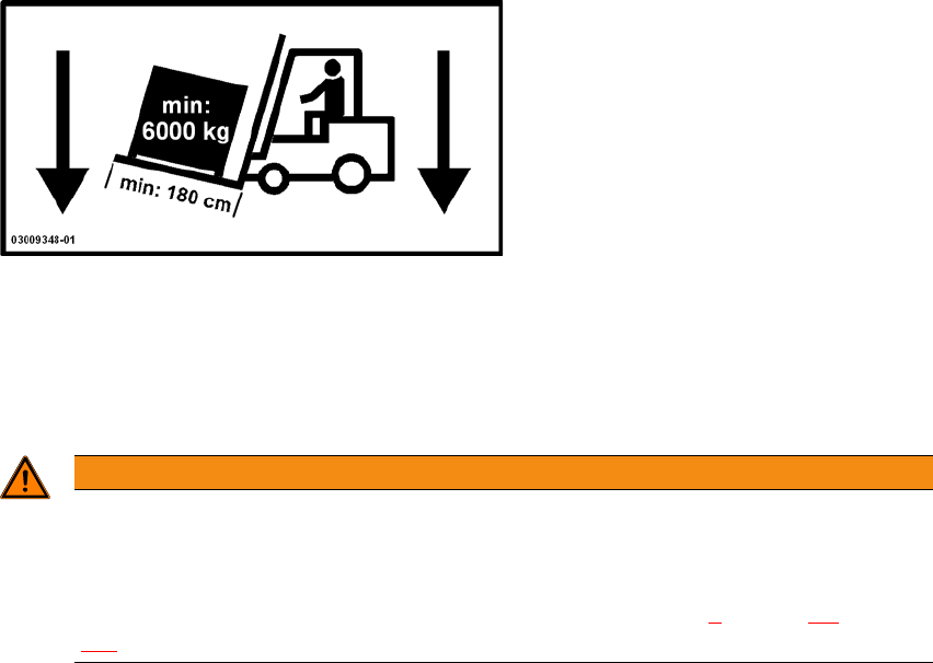
Use a fork-lift truck with the following specification to carry the placement machine:
Fork length: Min. 1800 mm
Carrying power: Min. 6000 kg
Clear width between forks: Min. 350 mm 2
2
WARNING
Risk of tilting!
Risk of tilting, if the required specifications for the fork-lift truck are not observed.
Only use the specified fork-lift for transportation.
Transportation of the placement machine is described in chapter 4
, section 4.1, page
143
.