00198382-03_UM_SIPLACE-CA4-V2_EN.pdf - 第74页
2 Operational safety Instruction manual SIPLACE CA4 V2 2.6 Safety features From software version 713.0 Edition 12/2019 74 2.6.3 Switches and buttons on the placement machine 2.6.3.1 Position of switches and buttons on th…
Instruction manual SIPLACE CA4 V2 2 Operational safety
From software version 713.0 Edition 12/2019 2.6 Safety features
73
2
2
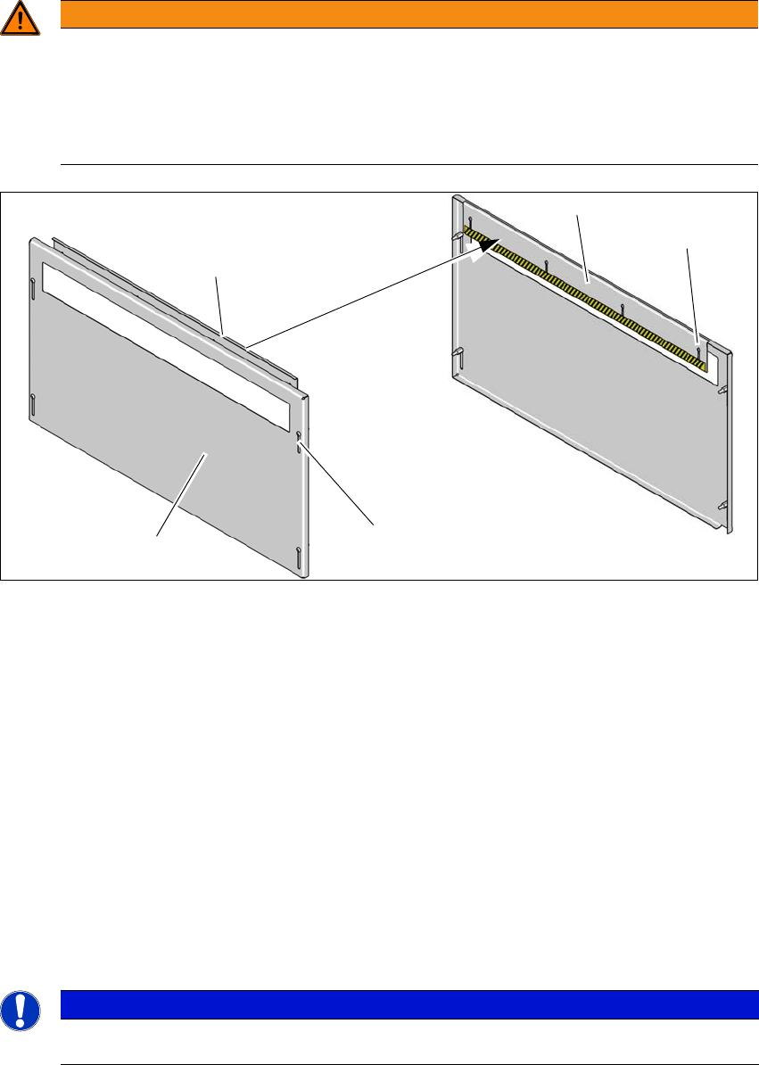
Fig. 2.6 - 3 Hand guard - inside and outside
(1) Hand guard - view from outside
(2) Hand guard - view from inside
(3) Slots on hand guard for height adjustment - outside
(4) Slots on hand guard for height adjustment - inside
Fit the hand guard (1) to the input conveyor and to the output conveyor.
Use the slots (3) to adjust the height on the outer plate for each product so that nobody can
reach into the board conveyor from below.
Use the slots (4) to adjust the height on the inner plate for each product so that nobody can
reach into the board conveyor from above.
Adjust the height so that the board with the components can be transported safely through
the conveyor system.
2
WARNING
DANGER OF CRUSHING!
If the hand guard is not fitted, reaching into the board conveyor could lead to injuries to
the arms and hands.
The operating company is responsible for ensuring that the hand guard is fitted.
Only operate the SIPLACE CA4 V2 if the hand guard is fitted.
PLEASE NOTE
2
Bear in mind the maximum height of the board with the highest component.
(1)
(2)
(2)
(3)
(4)
2 Operational safety Instruction manual SIPLACE CA4 V2
2.6 Safety features From software version 713.0 Edition 12/2019
74
2.6.3 Switches and buttons on the placement machine
2.6.3.1 Position of switches and buttons on the placement machine
2
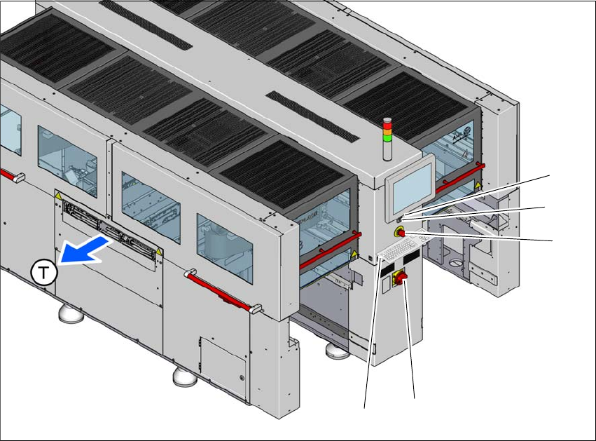
Fig. 2.6 - 4 Position of switches and buttons - location 3/4
(1) Start button (white)
(2) Stop button (black)
(3) EMERGENCY STOP button
(4) Main switch
(5) Button for docking and undocking the component trolley at the respective location
(T) Direction of PCB conveyor
(3)
(1)
(4)
(2)
(5)
Instruction manual SIPLACE CA4 V2 2 Operational safety
From software version 713.0 Edition 12/2019 2.6 Safety features
75
2
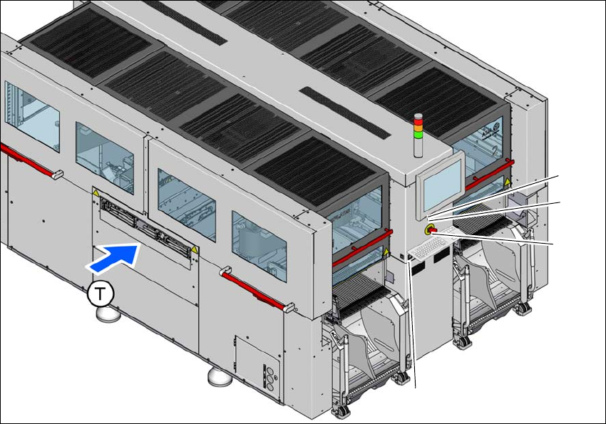
Fig. 2.6 - 5 Position of switches and buttons - location 1/2
(1) Start button (white)
(2) Stop button (black)
(3) EMERGENCY STOP button
(4) Button for docking and undocking the component trolley at the respective location
(T) Direction of PCB conveyor
(3)
(1)
(4)
(2)