00198382-03_UM_SIPLACE-CA4-V2_EN.pdf - 第75页
Instruction manual SIPLACE CA4 V2 2 Operational safety From software version 713.0 Edition 12/2019 2.6 Safety features 75 2 Fig. 2.6 - 5 Position of switches and buttons - location 1/2 (1) S tart button (white) (2) S top…
2 Operational safety Instruction manual SIPLACE CA4 V2
2.6 Safety features From software version 713.0 Edition 12/2019
74
2.6.3 Switches and buttons on the placement machine
2.6.3.1 Position of switches and buttons on the placement machine
2
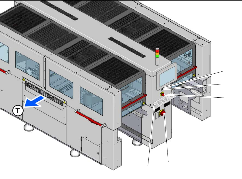
Fig. 2.6 - 4 Position of switches and buttons - location 3/4
(1) Start button (white)
(2) Stop button (black)
(3) EMERGENCY STOP button
(4) Main switch
(5) Button for docking and undocking the component trolley at the respective location
(T) Direction of PCB conveyor
(3)
(1)
(4)
(2)
(5)
Instruction manual SIPLACE CA4 V2 2 Operational safety
From software version 713.0 Edition 12/2019 2.6 Safety features
75
2
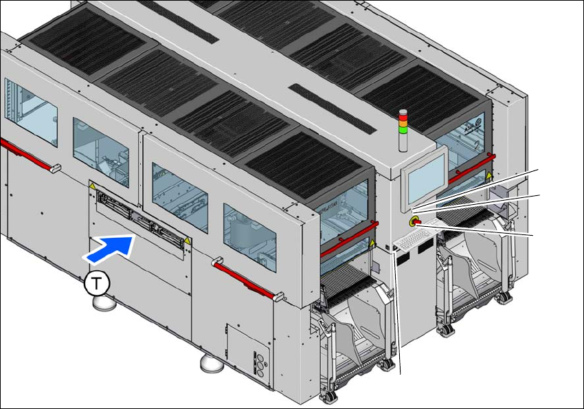
Fig. 2.6 - 5 Position of switches and buttons - location 1/2
(1) Start button (white)
(2) Stop button (black)
(3) EMERGENCY STOP button
(4) Button for docking and undocking the component trolley at the respective location
(T) Direction of PCB conveyor
(3)
(1)
(4)
(2)
2 Operational safety Instruction manual SIPLACE CA4 V2
2.6 Safety features From software version 713.0 Edition 12/2019
76
2.6.3.2 Position of the position switches on the placement machine
2
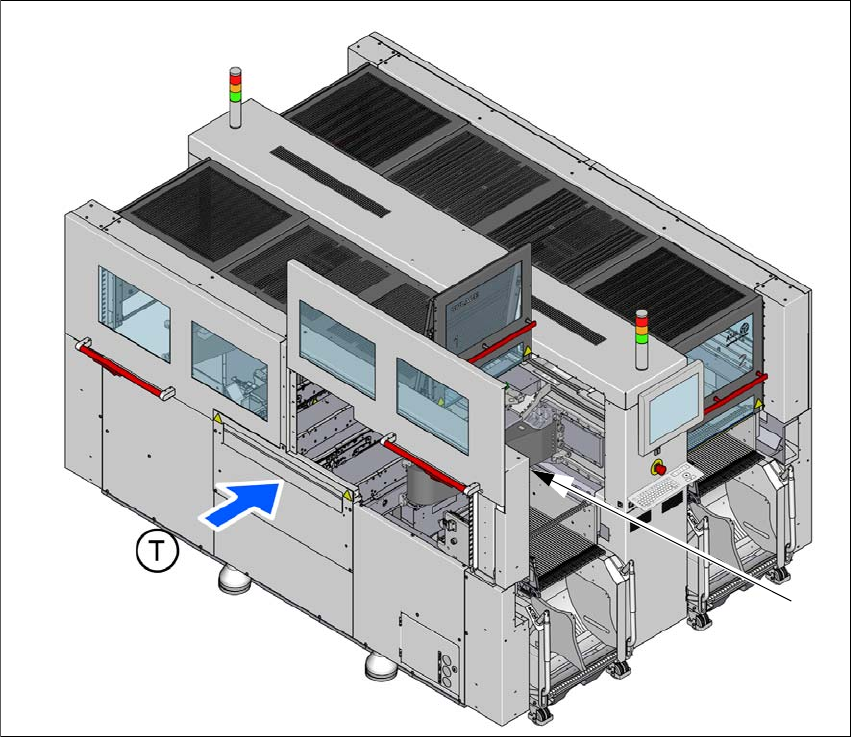
Fig. 2.6 - 6 Position of position switches on the placement machine
(1) Position switch, side sliding door location 1
(2) Position switch, protective cover location 1 (behind item 1)
(T) Direction of PCB conveyor
The position switches for the protective covers and side sliding doors at locations 2 to 4 are iden-
tical as those for location 1.
(1) + (2)