00198382-03_UM_SIPLACE-CA4-V2_EN.pdf - 第87页
Instruction manual SIPLACE CA4 V2 2 Operational safety From software version 713.0 Edition 12/2019 2.8 Disabling the com pressed air supply and d ischarging the pr essure 87 2.7.5 Compressed air conditions in the p lacem…
2 Operational safety Instruction manual SIPLACE CA4 V2
2.7 Residual voltages and discharge times in the placement machine From software version 713.0 Edition 12/2019
86
2
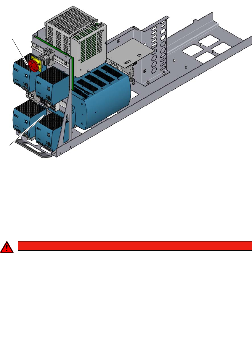
Fig. 2.7 - 1 Power supply unit, front view
(1) Main switch (S1)
(2) Mains terminals (X94) for the power supply cable
2.7.4 Main switch switched off - placement machine disconnected from the mains
power supply
2
(1)
(2)
DANGER
Lethal voltages in the power supply unit!
The power supply unit has components (capacitors) which can still conduct potentially le-
thal voltages for approx. 5 minutes, even when the placement machine has been switched
off and the mains plug has been disconnected.
When working on the power supply, switch off the main switch, secure it to prevent
switching on again, disconnect the placement machine from the power network and
wait 5 minutes until the capacitors have discharged.
Test to check that there is no remaining voltage supply. See the procedure described
in the service manual.
Only ASM Assembly Systems GmbH&Co.KG service engineers or the machine
owner's service engineers, who have been trained by ASM, may perform work on the
power supply and the safety cutoff (CBS).
Instruction manual SIPLACE CA4 V2 2 Operational safety
From software version 713.0 Edition 12/2019 2.8 Disabling the compressed air supply and discharging the pressure
87
2.7.5 Compressed air conditions in the placement machine after switching off at
the main power switch
When the main switch is switched off or the mains supply to the placement machine fails, the elec-
trically-controlled main valve of the compressed air unit will close (item 1 in fig. 2.8 - 1
, page 88 ).
The pressure will drop to 0 MPa (0 bar) within 5 seconds. The components before the electrically-
controlled main valves will remain pressurized.
2.8 Disabling the compressed air supply and discharging
the pressure
The compressed air unit is located in the sector distributor of location 1 (see fig. 4.2 - 1, page 152
). The working pressure of the placement machine is set to 0.50 ± 0.025 MPa (5.0 ± 0.25 bar). The
position of the compressed air unit is shown at item 1 in fig. 2.8 - 1
, page 88. The supply of com-
pressed air to the placement machine can be interrupted with the shutoff valve (item 2 in fig. 2.8
- 1, page 88 ).
Use the machine key to release the cover lock.
Lift the cover (see fig. 2.8 - 1, page 88 ).
Turn the lever of the shutoff valve (item 2 of fig. 2.8 - 1, page 88) from the vertical to the hor-
izontal position.
Pay attention to the operating pressure manometer. When the placement machine is
switched on, the pressure discharges to 0 MPa (0 bar) within 1 minute.
Secure the compressed air unit by closing the shutoff valve with a lock (item 2 in fig. 2.8 - 1,
page 88
)
2
CAUTION
Interruption to compressed air supply!
When the placement machine is switched on, do not use the stop valve to interrupt
the compressed air supply for more than 30 minutes.
If you need to shut off the pneumatic system for longer in order to carry out preven-
tive maintenance or servicing work, you must switch the placement machine off at
the main switch and disconnect it from the power supply.
2 Operational safety Instruction manual SIPLACE CA4 V2
2.8 Disabling the compressed air supply and discharging the pressure From software version 713.0 Edition 12/2019
88
2
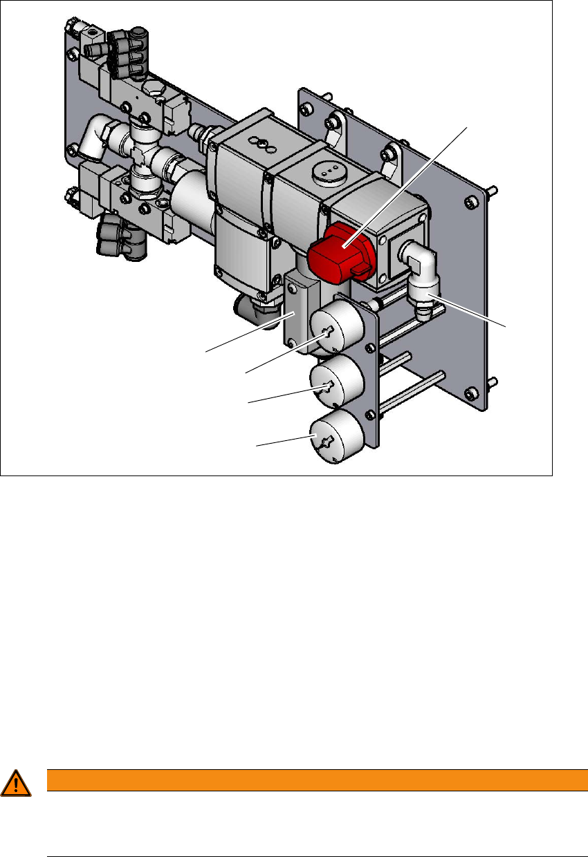
Fig. 2.8 - 1 Compressed air unit on the placement machine
Legend for fig. 2.8 - 1
(1) Compressed air filter
(2) Shutoff valve in the "OPEN" position (lockable)
(3) Compressed air connection
(4) Manometer for the machine component supply pressure
Target pressure: 0.5 ± 0.025 MPa, 5 ± 0.25 bar (display range 0 - 1.0 MPa, 0 - 10 bar)
(5) Manometer for supply pressure of gantries 1 to 4
Target pressure: 0.46 ± 0.01 MPa, 4.6 ± 0.1 bar (display range 0 - 1.0 MPa, 0 - 10 bar)
(6) Manometer for inlet pressure
Target pressure: 0.5 - 1.0 MPa, 5 - 10 bar (display range: 0 - 1.0 MPa, 0 - 10 bar)
2
WARNING
Risk of injuries!
Risk of injuries from pressurized compressed air lines.
NEVER detach compressed air lines while they are still pressurized.
(6)
(1)
(3)
(2)
(5)
(4)