EUKYX-199-2100_G5S2_Instruction_Vol2_E.pdf - 第124页
EUKYX 2-1 1 199-2100 3.1 Common SET 3 . Explana ti on of P at tern P rog ra m In thi s in struction manu al , t he pl acement c oordin ate ref erence is based on “Fron t Righ t” . 3. 1 Common SET Thi s dat a is u sed in …
EUKYX
2-10199-2100
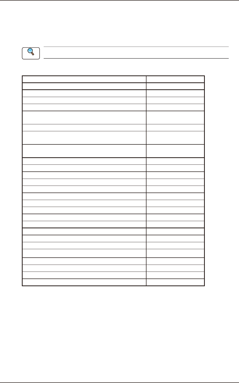
2.7 Composition of Placement Data
2.7 Composition of Placement Data
The set parameters are used to place the components (IDs in the placement feeder location data) on
the points with the specified coordinates in the designated direction.
One step is allocated for each component to be placed.
Refer to 3.7 Placement in this chapter for the details of each item.
G01 Placement Data
Items Ref. No.
Un (G01_01)
Offset Data (G02)
Offset (G02)
Unit Control (G02_01)
Offset
X [mm], Y [mm], Z [ ° ], H [mm]
(G02_02)
Unit PCB Fiducial (G02_03)
Recog Coord
X1, Y1, X2, Y2
(G02_04)
Fiducial Mark
FM1, FM2
(G02_05)
P-Data (G03)
PNo. (G03_01)
X [mm], Y[mm] (G03_02)
Z [ ° ] (G03_03)
H [mm] (G03_04)
Component ID (G03_05)
Fdr. No. (G03_06)
Symbol (G03_07)
C (G03_08)
Comment (G03_09)
O-Data (G04)
Ono. (G04_01)
X [mm], Y[mm] (G04_02)
Z [ ° ] (G04_03)
H [mm] (G04_04)
C (G04_05)
Comment (G04_06)
B-X, B-Y (G04_07)
Reference
EUKYX
2-11199-2100
3.1 Common SET
3. Explanation of Pattern Program
In this instruction manual, the placement coordinate reference is based on “Front Right”.
3.1 Common SET
This data is used in the dual transfer operation (option).
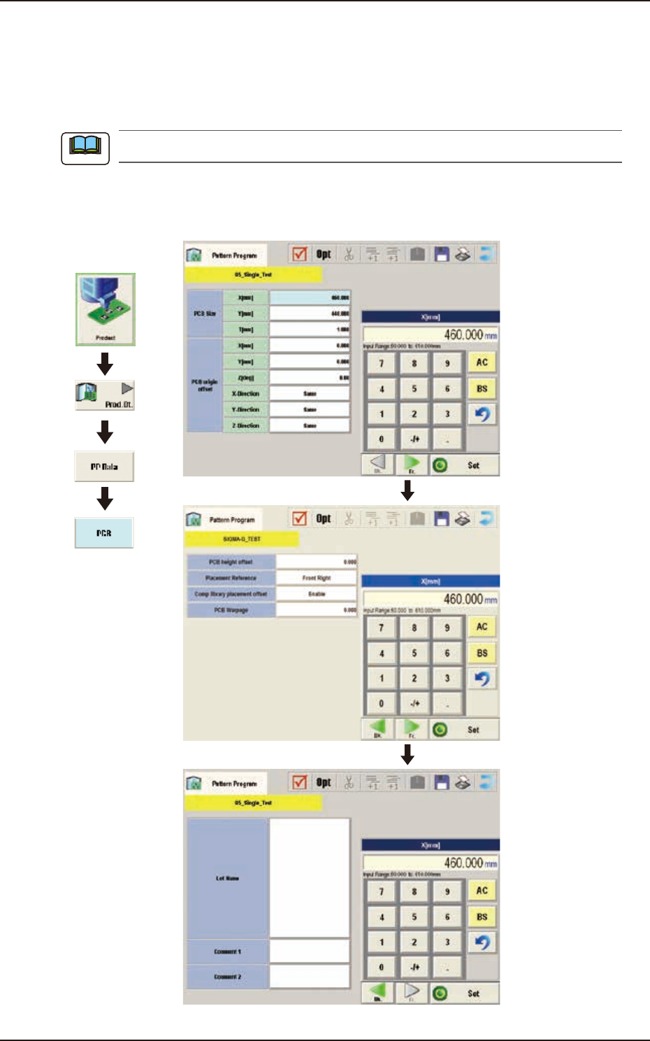
3.2 PCB
(B01) PCB Data
Graphic
Development
F2B3
Note

EUKYX
2-12199-2100
3.1 Common SET
(B01_01)
PCB size
X (Horizontal), Y (Vertical), and T (thickness) [mm]
Set the dimensions of the PCB to be produced.
Y (Vertical)
T (Thickness)
PCB
X (Horizontal)
PCB Flow Direction
F2B4
When the PCB has a cutout, the following dimensions must be entered.
Y (Vertical)
T (Thickness)
PCB
X (Horizontal)
PCB Flow Direction
F2B5
• Data Input Range
X : 50 to 610
Y : 50 to 510
T : 0.3 to 5.0
(a) Be sure to set a correct parameter in the "X (Horizontal)" text box because the set
parameter is used to automatically correct the placement position when a parameter is
selected in the "PCB locate method" text box in the "PCB transfer Mode Setup" tab sheet.
(b) The set parameter in the "Y (Horizontal)" text box must be used as a target width for the
conveyor width automatic adjustment operation.
(c) "T (Thickness)" is used as a target value for the backup table ascending position when a
PCB is clamped by the clamp plates and positioned.
Note