EUKYX-199-2100_G5S2_Instruction_Vol2_E.pdf - 第129页
EUKYX 2-16 199-2100 3.1 Common SET ( B 01_ 0 4 ) PCB Po sitioning Reference Set the P CB positi oni ng reference in th is text b ox . The reference must be specifi ed accordi ng to the input and output mach ines. Rear Le…
EUKYX
2-15199-2100
3.1 Common SET
(B01_03)
PCB height offset [mm]
Set an offset value as a nozzle descending distance based on the upper surface of the PCB in the
component placement section. This offset value applies to all components in the pattern program.
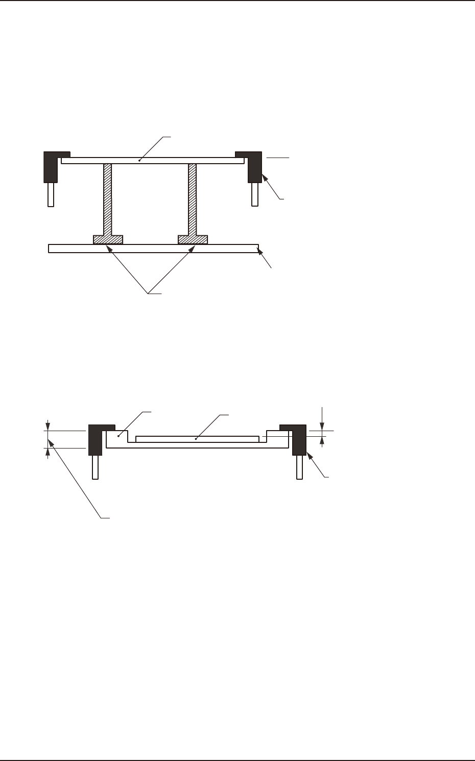
Normal Cases
Set "+0.000" (zero) in the text box. The figure below shows that the upper surface of a PCB is
maintained by the PCB support pins at the PCB upper surface reference.
PCB
PCB Upper Surface
Reference
Chute
Backup Pin
Backup Table
F2B9
Example of Jig PCB Usage
The figure below shows that the upper surface of a PCB is lower than the PCB upper surface
reference. If "PCB Upper Surface Reference + a" is set as an offset value at this time, components
can be placed correctly on the PCB.
a
T (Thickness)
Jig PCB
PCB
PCB Upper Surface
Reference
Chute
F2B10
EUKYX
2-16199-2100
3.1 Common SET
(B01_04)
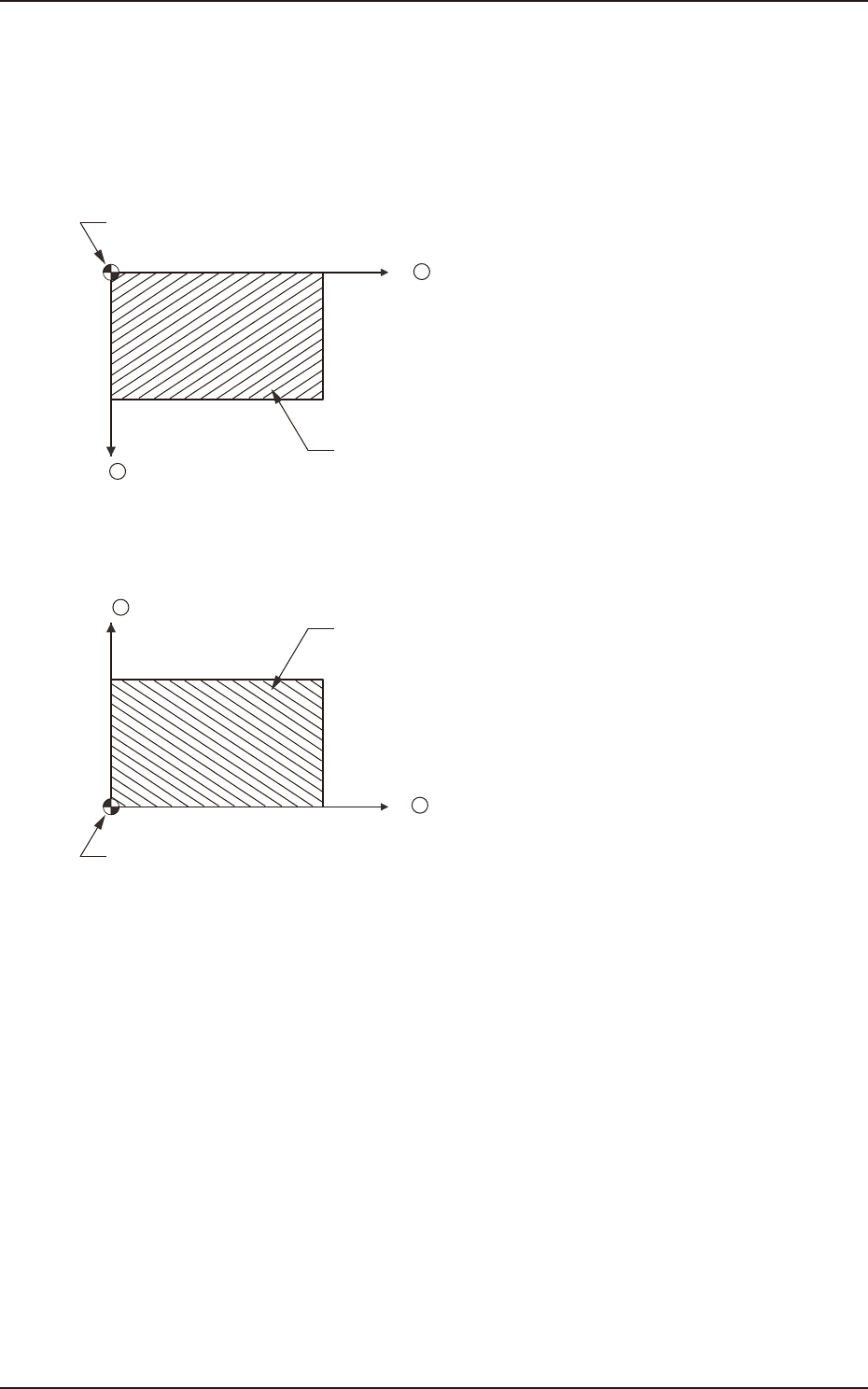
PCB Positioning Reference
Set the PCB positioning reference in this text box. The reference must be specified according to the
input and output machines.
Rear Left : The placement coordinate reference is based on the rear left side and specified as
follows.
X +
Y +
Placement Coordinate Reference (No)
PCB
F2B11
Front Left : The placement coordinate reference is based on the front left side and specified as
follows.
X +
Y +
Placement Coordinate Reference (No)
PCB
F2B12
EUKYX
2-17199-2100
3.1 Common SET
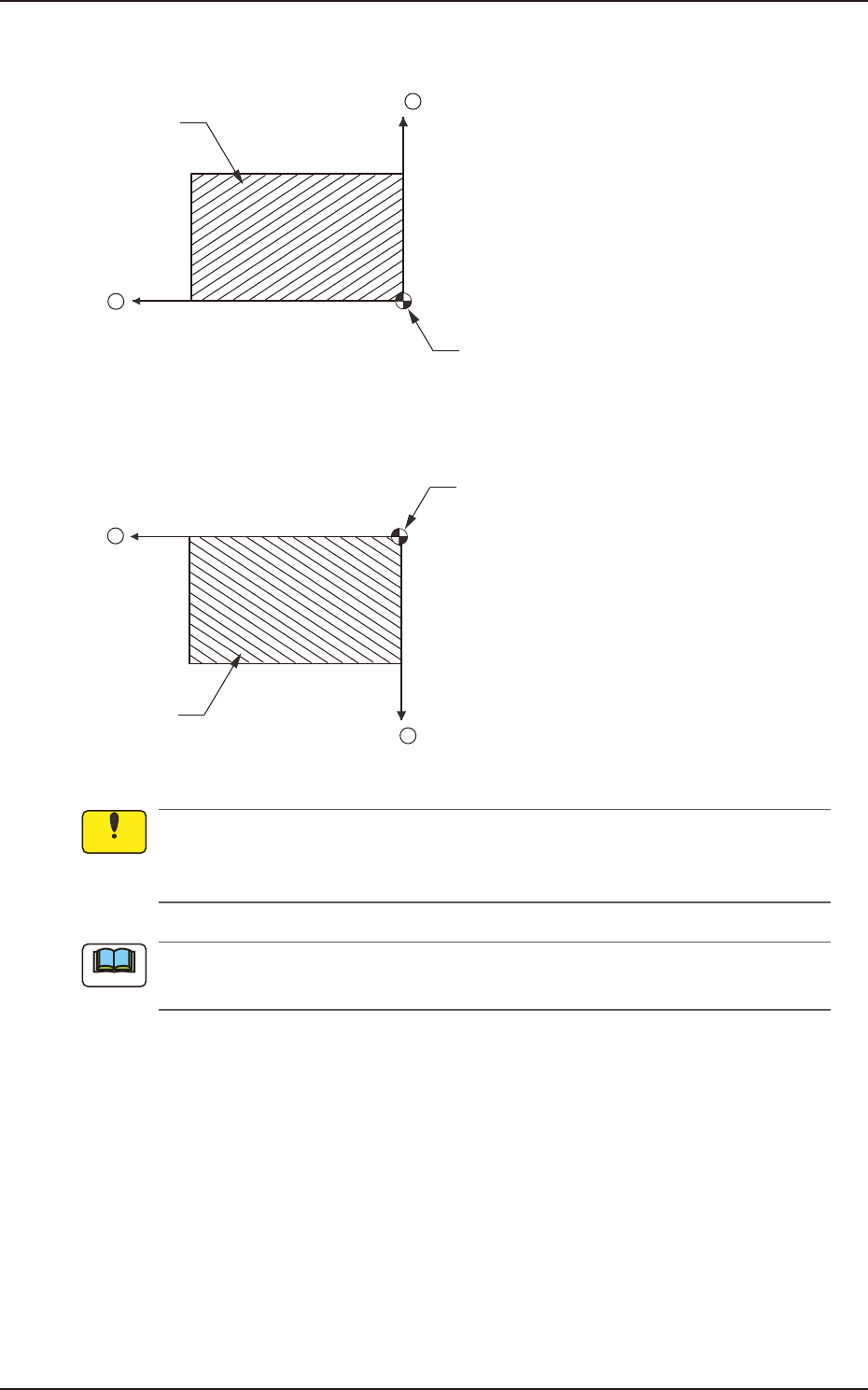
Front Right : The placement coordinate reference is based on the front right side and specified as
follows.
X +
Y +
Placement Coordinate Reference (No)
PCB
F2B13
Rear Right : The placement coordinate reference is based on the rear right side and specified as
follows.
X +
Y +
Placement Coordinate Reference (No)
PCB
F2B14
Be sure to set the same reference as the input and output machines.
If a reference different from the input and output machines is specified, PCBs cannot be
produced correctly.
When a different reference is specified in the pattern program and the program is to be used
for this machine, be sure to change the reference of this machine to the different one.
Notice
Note