EUKYX-199-2100_G5S2_Instruction_Vol2_E.pdf - 第102页
EUKYX 1-52 199-2100 4.2 . 1 3 Er ror diagnosis When the [ Error di agnos is] button is pressed on the " Opr . Mo de" tab shee t, the fol low in g wi ndow app ear s. F2A42B ► PEC Mar k s pan c he ck Fu nction Se…
EUKYX
1-51199-2100
4.2.11 Flux spread
When the [Flux spread] button is pressed on the "Opr. Mode" tab sheet, the following window appears.
F2A41A
It is set when the flux application unit (option) is used.
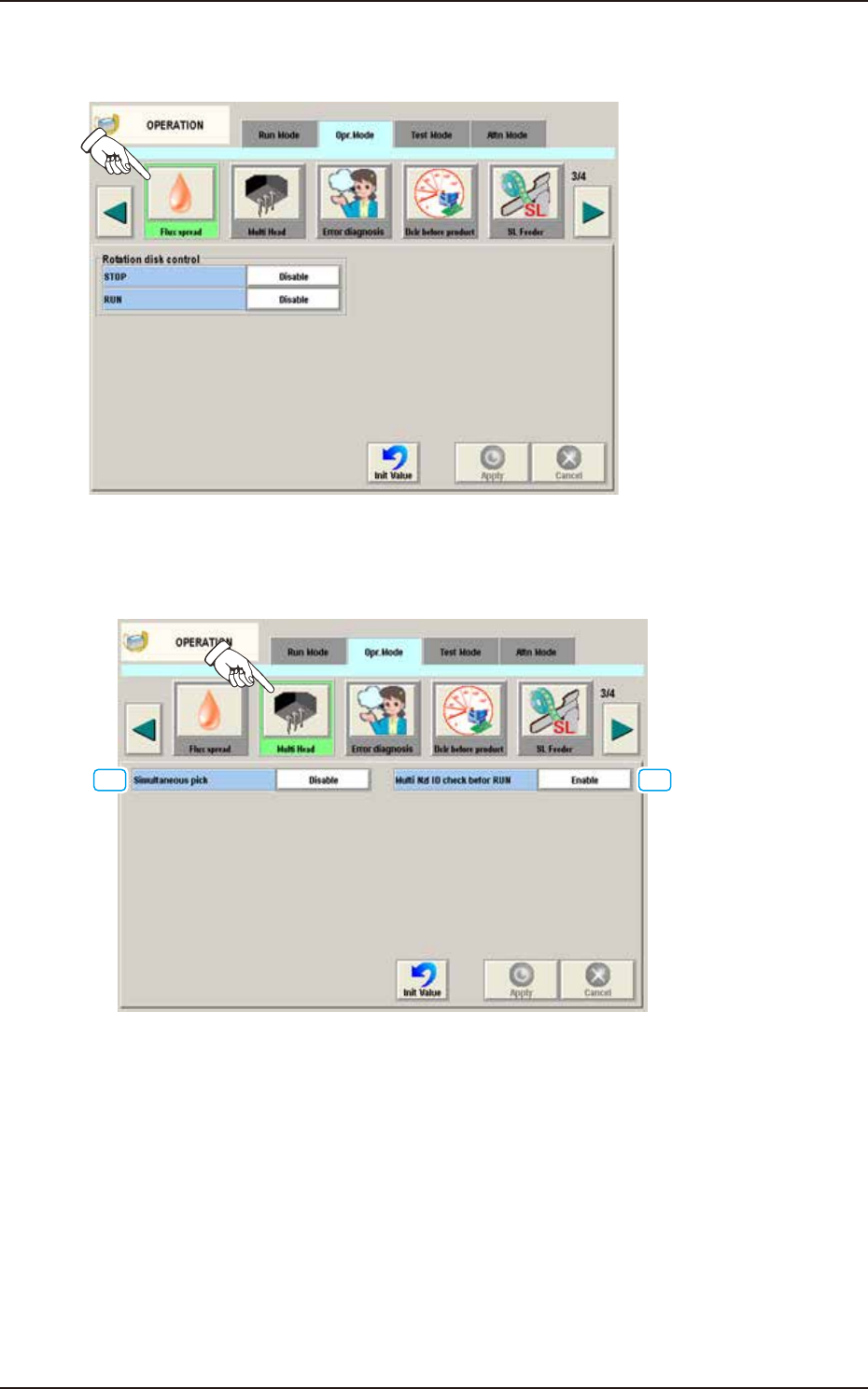
4.2.12 Multi Head
When the [Multi Head] button is pressed on the “Opr. Mode” tab sheet, the following window appears.
[1] [2]
F2A42A
[1] Simultaneous pick
The multi-functional head is used when the nozzle pitch of head agrees with the tape feeder pitch
for component pickup.
Enable : When selected, the component simultaneous pickup is performed.
Disable : When selected, the component simultaneous pickup is not performed.
[2] Multi Nzl ID check befor RUN
Enable : When selected, the ID of the nozzle housed in the nozzle stocker for the multi-
functional nozzle, is identified and the data is re-written in the case that the
identification result is not the same as that on the placement nozzle/head data.
Also, it is checked whether if all the nozzles required for the production, have
been prepared.
Disable : When selected, the nozzle ID recognition function is not used.
4.2 "Opr.Mode" Tab Sheet
EUKYX
1-52199-2100
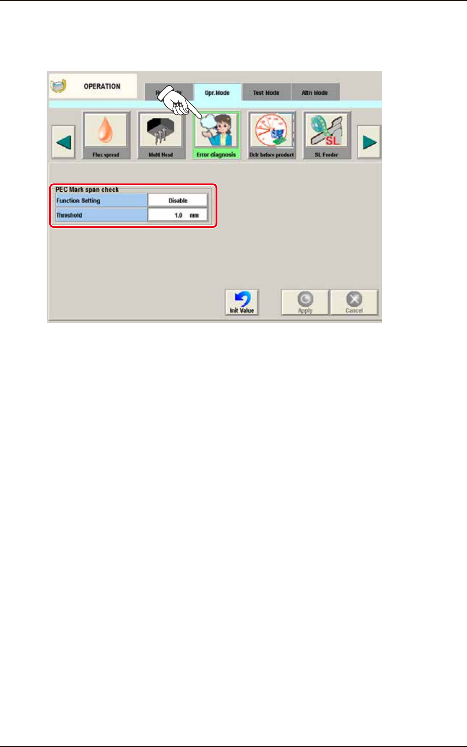
4.2.13 Error diagnosis
When the [Error diagnosis] button is pressed on the "Opr. Mode" tab sheet, the following window
appears.
F2A42B
►
PEC Mark span check
Function Setting
Select “Enable” or “Disable” for the function of abnormal stop when the distance between the PEC
Mark span exceeds the threshold.
Disable
Select this when PEC Mark span check is not used.
Enable
Select this when PEC Mark span check is used.
Threshold
Set the tolerance of the distance between PEC Mark span.
4.2 "Opr.Mode" Tab Sheet
EUKYX
1-53199-2100
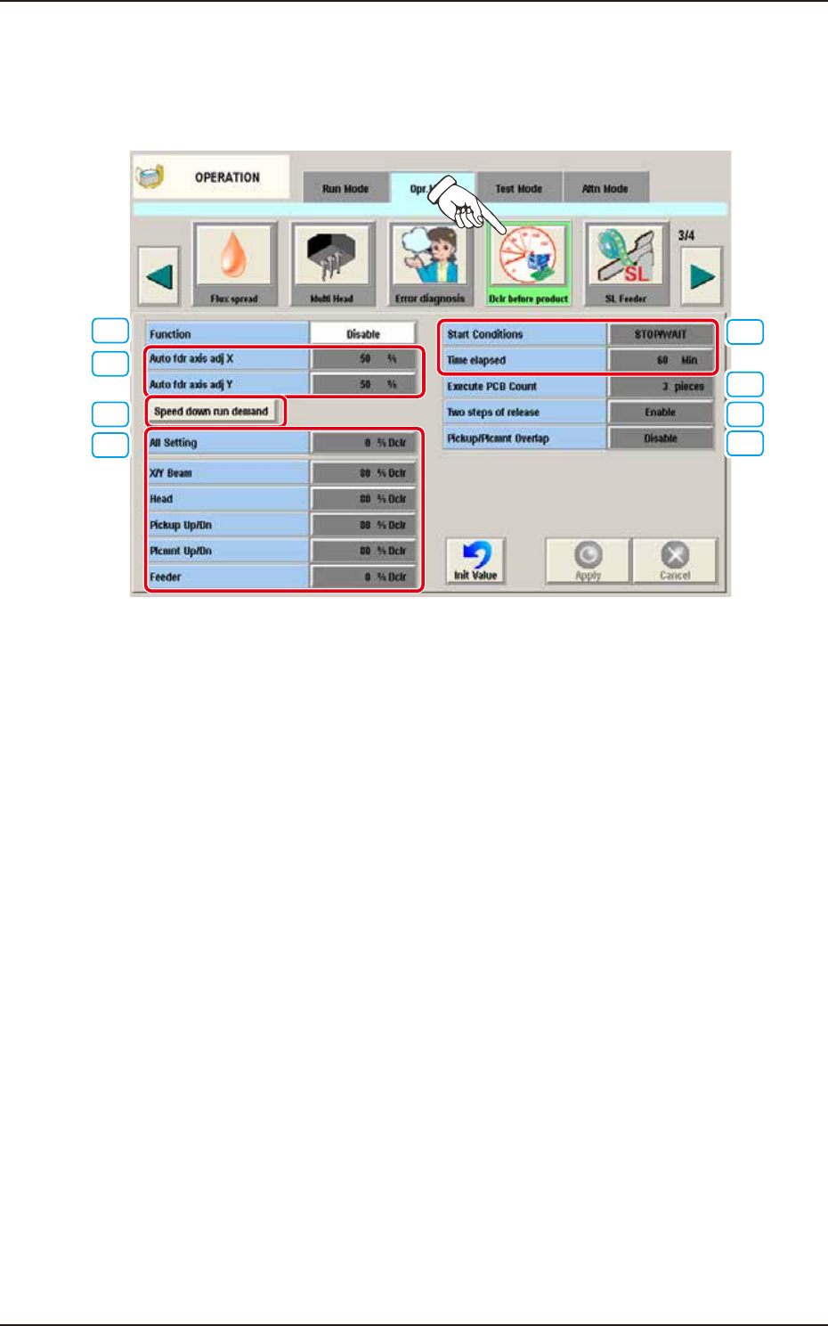
4.2.14 Dclr before product
This is the function to suppress the speed until the component pickup becomes stable during the
automatic operation right after the Setup. When the [Dclr before product] button is pressed on the
"Opr. Mode" tab sheet, the following window appears.
[1]
[2]
[3]
[4]
[5]
[6]
[7]
[8]
F2A42C
[1] Function
Disable
Select this when Dclr before product is not used.
Enable
Select this when Dclr before product is used.
[2] Auto fdr axis adj X, Auto fdr axis adj Y
Set the feedback amount for Pickup Auto Adjust.
[3] Speed down run demand button
Perform the Dclr before automatic operation.
4.2 "Opr.Mode" Tab Sheet