EUKYX-199-2100_G5S2_Instruction_Vol2_E.pdf - 第108页
EUKYX 1-58 199-2100 4.4 "Altn Mode" T ab Sheet 4.4 " Altn Mode " T ab Sheet When the [Altn Mode ] but ton is pressed, the " Altn M ode" tab she et appears. (a ) It is requ ired that the f ee…
EUKYX
1-57199-2100
4.3 "Test Mode" Tab Sheet
4.3 "Test Mode" Tab Sheet
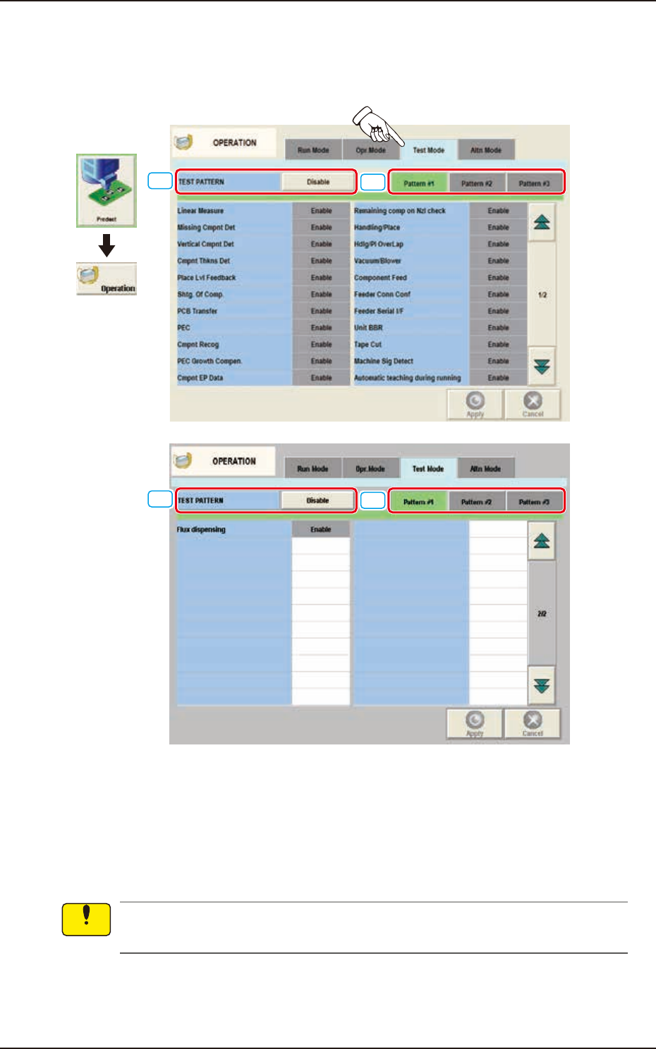
When the [Test Mode] tab is pressed on the "OPERATION" window, the following tab sheet
appears.
[1]
[2]
[1]
[2]
Graphic
Development
F2A43
The number of test run patterns to be saved is up to three.
[1] TEST PATTERN
The pattern where the test operation mode has been designated, is selected in this data box.
[2] [Pattern #1], [Pattern #2], and [Pattern #3] Buttons
Select one of the buttons to specify the desired pattern for designation of the test mode.
Wrong selections (test run in wrong modes) will cause various deficiencies such as component
picks by vacuum nozzles, scattering of components, or collision with the chute, etc.
Notice
EUKYX
1-58199-2100
4.4 "Altn Mode" Tab Sheet
4.4 "Altn Mode" Tab Sheet
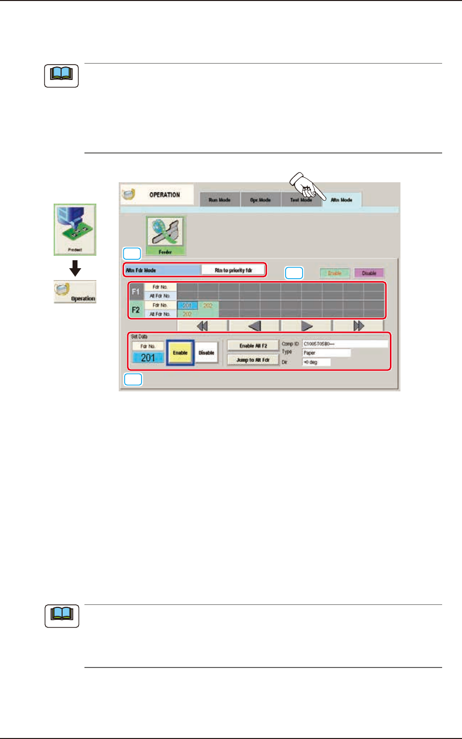
When the [Altn Mode] button is pressed, the "Altn Mode" tab sheet appears.
(a) It is required that the feeder "Alternate" function is setup in the pattern program, in
advance.
(b) The parameters specified here become valid prior to the other alternate-related ones that
are designated in the pattern program.
Even when "Enable" is set in the pattern program, this alternate feeder mode can be
used to temporarily set "Disable" in relation to preparation for the feeders.
[1]
[2]
[3]
Graphic
Development
F2A44
[1] Altn Fdr Mode
[Disable] Button
When pressed, this button invalidates the alternate feeder mode.
In this case, the contents of the window are changed.
[Rtn to priority fdr] Button
When selected, the "Feeder Alternate" function is enabled.
The components of the specified feeder No. are alternated.
[Keep current fdr] Button
When selected, the “Feeder Alternate” function is enabled.
After the components on the specified feeder No., are used up, when there is any other
feeder with the same components, such feeder is used until the components on the feeder
are used up.
(a) The feeders on the opposite block are to be used in this “Feeder Alternate” operation.
(b) The use of the high-speed head or multi-functional head is available.
(c) The multi-layered tray or vibration stick feeder is not available.
(d) Same Component: Component with the same Component ID
Note
Note
EUKYX
1-59199-2100
4.4 "Altn Mode" Tab Sheet
[2] F1 and F2
The feeder Nos. and the destination feeder Nos. are colored, indicating whether the alternate feeder
mode is “enabled” or “disabled”.
Light Blue : Enable
Pink : Disable
"Disable" is automatically set for the feeder No. where a component shortage error is detected.
When a feeder is set after component replenishment, "Enable" is automatically set.
[3] "Set Data" Group Box
The Feeder No. selected in [2] appears in the "Fdr No." text box.
[Enable] and [Disable] Buttons
When the feeder whose parameter "Enable" or "Disable" for the feeder alternate function
must be changed is selected and the [Enable] or the [Disable] button is pressed, the
parameter can be changed manually.
[Enable All F1] Button, [Enable All F2] Button
"Enable" is set for all feeders on the feeder base selected in [2] (Feeder Base #1 in the
window).
[Jump to Alt Fdr] Button
The feeder Nos. selected in [2] are specified as the destination ones for the alternate feeder
mode.
Comp ID, Type, and Dir
Displayed are the component ID, type and angle of the feeder No. selected in [2].
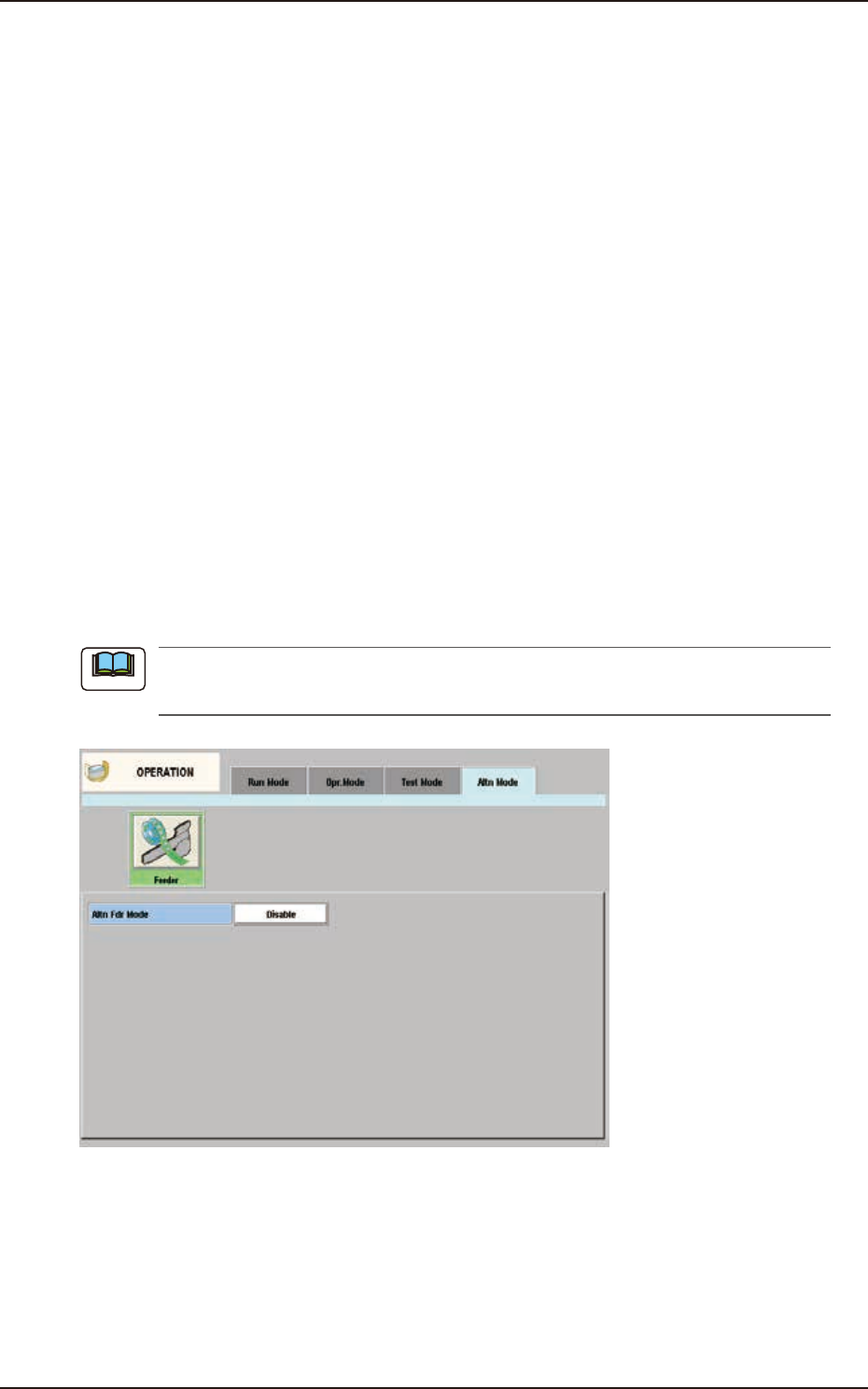
When “Disable” is set for the alternate feeder mode in the pattern program, the “Altn Mode”
window is changed as follows.
F2A45
Note