EUKYX-199-2100_G5S2_Instruction_Vol2_E.pdf - 第113页
199-2100 Chapt er 2 Pattern Program This chapter describes of the pattern program. 1. Outline of Pattern Program 2. Composition of Pattern Program 3. Explanation of Pattern Program EUKYX
EUKYX
1-62199-2100
7. "Recall" Submenu
7. "Recall" Submenu
Graphic
Development
MTN:NotRdy RCG:NotRdy
F2A48
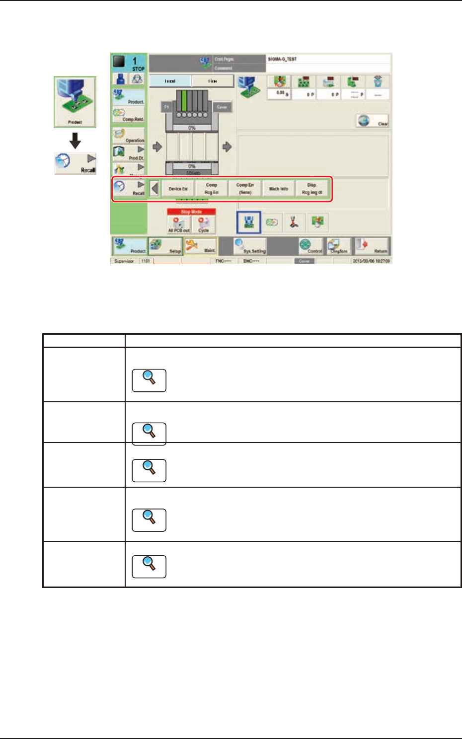
The "Recall" submenu is provided with the following five buttons.
When a button is pressed, the corresponding window opens, enabling the operator to select the
required data.
Buttons Description
Device Err When pressed, the device error history is displayed.
Reference
Refer to “2. “Device Err” Window” in Chapter 5 for the details.
Comp Rcg Err When pressed, the component recognition error history is displayed.
Reference
Refer to “3. “Comp Rcg Err” Window” in Chapter 5, for the details.
Comp Err(Sens) When pressed, the detected component posture error history is displayed.
Reference
Refer to “4. “Comp Err(Sens)” Window” in Chapter 5, for the details.
Mach Info When pressed, the machine information history is displayed.
Reference
Refer to “5. “Mach Info” Window” in Chapter 5, for the details.
Disp. Rcg img dt When pressed, the "Disp. Rcg Img Dt" window appears.
Reference
Refer to “6. “RECOG IMAGE” Window” in Chapter 5, for the details.

199-2100
Chapter 2
Pattern Program
This chapter describes of the pattern program.
1. Outline of Pattern Program
2. Composition of Pattern Program
3. Explanation of Pattern Program
EUKYX
EUKYX
2-1199-2100
1. Outline of Pattern Program
1. Outline of Pattern Program
[1]
[2]
[3]
[4]
Graphic
Development
F2B1
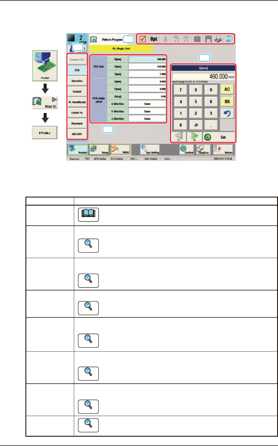
[1] Pattern Program Menu
The “Pattern Program Menu”window is provided with the following eight menu items. When each
button is pressed, the corresponding window appears.
Windows Description
Common SET
Note
This window is used for dual transfer (Option).
PCB Using these parameters, the PCB size and reference, etc. are set in this window.
Reference
Refer to”3.2 PCB” in this chapter for the details.
Operation Using these parameters, the PEC recognition mark used in the PEC recognition
operation, is set in this window.
Reference
Refer to “3.3 Operation” in this chapter for the details.
Control Using these parameters, the automatic operation is controlled.
Reference
Refer to “3.4 Control” in this chapter for the details.
PL Head/Nozzle Using these parameters, the nozzle is placed on the specified position (Placement
Nozzle/Head No.) in the head.
Reference
Refer to “3.5 PL Head/Nozzle” in this chapter for the details.
CMPNT PL Using these parameters, the component IDs (component types) to be arranged in
each fdr No. (Feeder No.), are set.
Reference
Refer to “3.6 CMPNT PL” in this chapter for the details.
Placement Using these parameters, the components in the component arrangement data are
set to place them on the specified coordinate position and in the specified direction.
Reference
Refer to “3.7 Placement” for the details.
HDLG/PL
Reference
Refer to “ 3. 8 H D LG / PL” in this chapter for the details.