EUKYX-199-2100_G5S2_Instruction_Vol2_E.pdf - 第145页
EUKYX 2-32 199-2100 3.3 Operation (C05_05) M- X, M- Y Us ing these selec tion box es, the suppor t pin p la cement coordi nates ( M-X, M- Y ) are setup. Coord X, Coord Y The set suppor t pin c oordin ates are d isp la ye…
EUKYX
2-31199-2100
3.3 Operation
(C05_02)
Support Pin
Using this selection button, it is set whether or not the support pins are setup automatically in the
pattern program change operation.
(C05_03)
The number of Pin using
The number of pins to be used in the automatic operation is set in this selection box.
• Data Input Range: 1 to 20 pins
(C05_04)
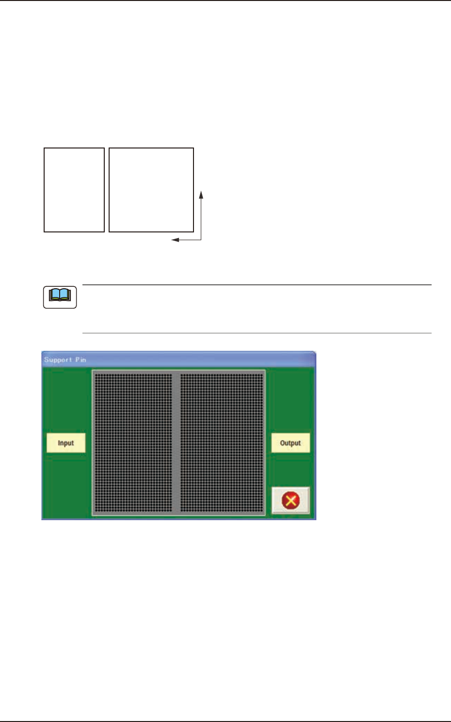
Table
Using this selection box, it is set that the backup base where the support pins are placed, is in the
output or input.
Input Output
Backup Base
F2B27
EUKYX
2-32199-2100
3.3 Operation
(C05_05)
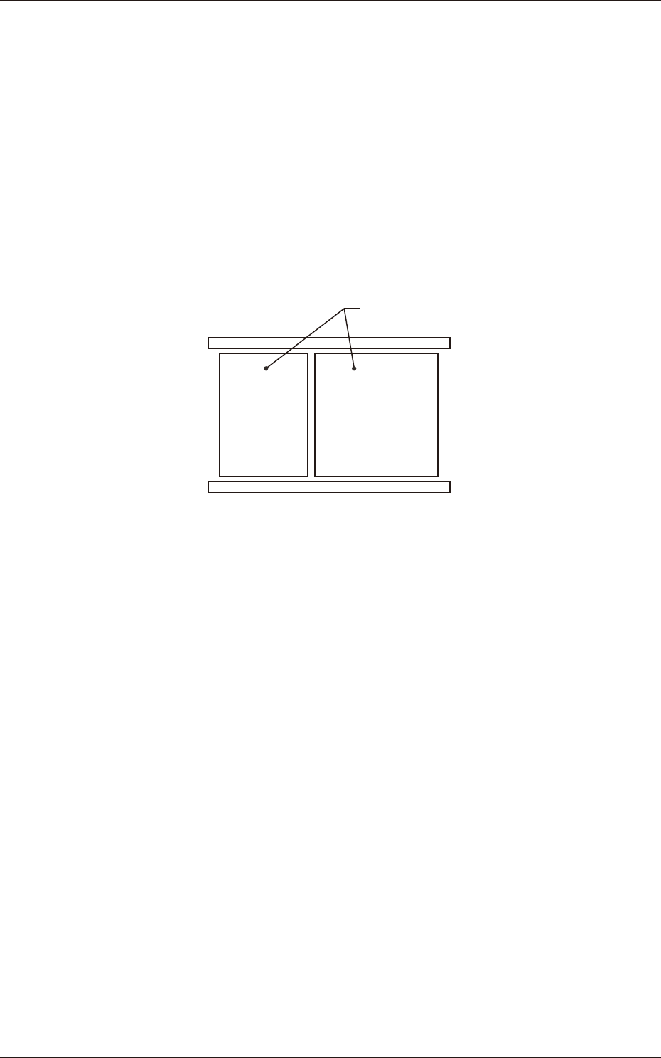
M-X, M-Y
Using these selection boxes, the support pin placement coordinates (M-X, M-Y) are setup.
Coord X, Coord Y
The set support pin coordinates are displayed in these data boxes.
• Data Input Range
Input: M-X : 1 to 30 / M-Y : 1 to 50
Output: M-X : 1 to 30 / M-Y : 1 to 50
Y
X
Input Output
F2B28
When the [Pin] button is pressed, the "Support Pin" dialogue box is opened and the support
pin positions can be checked.
When the [Clear] button is pressed, the support pins with the selected Nos. are cleared.
F2B29
Note
EUKYX
2-33199-2100
3.4 Control
3.4 Control
(D01) Control Data
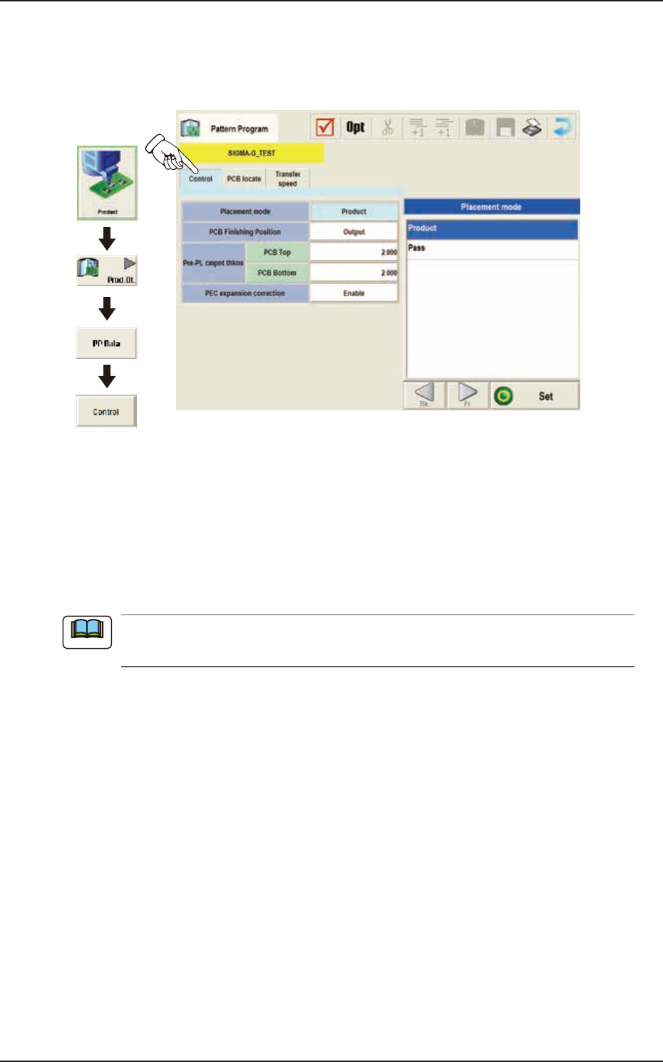
When the [Control] tab is pressed in the "Control" window, the following tab sheet appears.
Graphic
Development
F2B30
(D01_01)
Placement Mode
"Product" or "Pass" is selected for the placement mode in this pane.
Normally, "Product" is selected.
Product : When selected, the placement operation is performed.
Pass : When selected, the PCB is passed without placement.
When the pattern program set to "Pass" is setup on the Pattern Program Data on “Setup“
- “Prgm Chg.“ window, the vacuum pump is automatically turned OFF.
Note