EUKYX-199-2100_G5S2_Instruction_Vol2_E.pdf - 第154页
EUKYX 2-41 199-2100 3.4 Control (D03) T ransf er Spe ed Da ta When the [ T ransfer Spe ed ] tab is pressed in the "Control"wi ndow , the foll owing tab sheet appears. Graphic Development F2B39

EUKYX
2-40199-2100
3.4 Control
(D02_09)
UP
MOVE
“Standard” or “Value Designation” is selected for the PCB positioning moving up operation.
Normally, “Standard” is selected.
Standard : The operation is performed based on the standard values set in
the machine.
Value Designation : For the operation procedure, the selected values can be setup.
1st speed DCLR SET
The speed reduction rate for the backup base first stage operation in the PCB positioning, is setup
in this data box. This value is reflected on the speed and acceleration.
2nd speed DCLR SET
The speed reduction rate for the backup base second stage operation in the PCB positioning, is
setup in this data box. This value is reflected on the speed and acceleration.
Vac. Ctrl. delayed starts
The time period from the backup base first stage operation start-up in the PCB positioning to the
vacuum pick-up turning ON, is set in this data box.
Vac. Wtg. Timer
The time period from the backup base first stage operation start-up in the PCB positioning to the
second stage operation start-up, is set in this data box.
Z clamp waiting time
The time period for judging for the Z-Clamp Moving-up Completion in the PCB positioning, is set in
this data box.
(D02_10)
DN
MOVE
"Standard" or "Value Designation" is selected for the PCB positioning moving -down operation.
Standard : The operation is performed based on the standard values set in the
machine.
Value Designation: For the operation procedure, the selected values can be setup.
1st speed DCLR SET
The speed reduction rate for the backup base first stage operation in the PCB positioning clearance
operation, is setup in this data box. This value is reflected on the speed and acceleration.
2nd speed DCLR SET
The speed reduction rate for the backup base second stage operation in the PCB positioning
clearance operation, is setup in this data box. This value is reflected on the speed and acceleration.
Vac. Ctrl. delayed starts
The time period from the operation start-up in the PCB positioning clearance operation to the
vacuum pick-up turning OFF, is set in this data box.
Vac. Wtg. Timer
The time period from the first stage operation completion to the second stage operation start-up in
the PCB positioning clearance operation, is set in this data box.
Damaged Vac. Wtg. time
The time period of the vacuum breakage ON operation in the PCB positioning clearance operation,
is set in this data box.
Backup axis DN start DLY
The time period until the backup base first stage operation start-up in the PCB positioning clearance
operation, is set in this data box.
EUKYX
2-41199-2100
3.4 Control
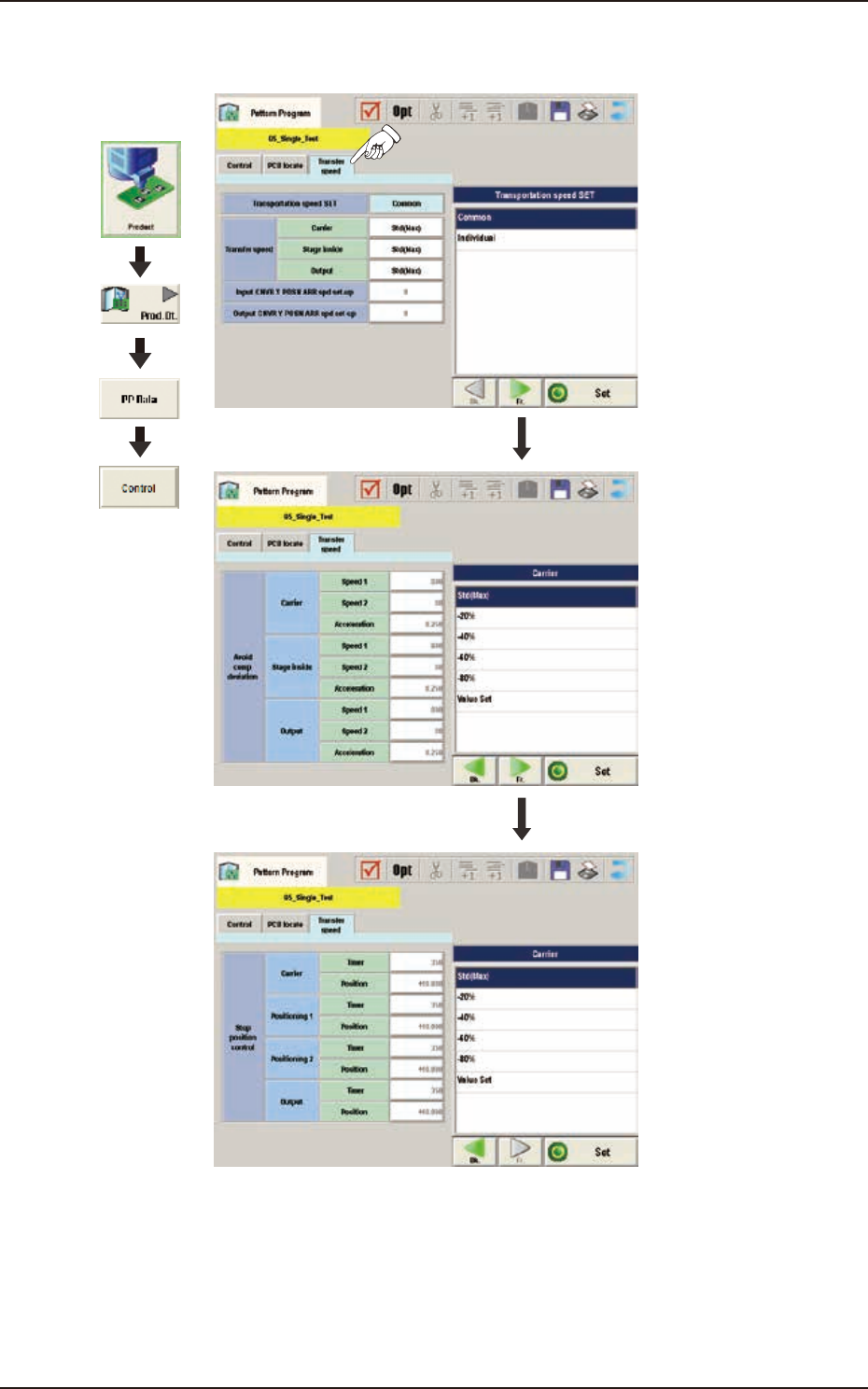
(D03) Transfer Speed Data
When the [Transfer Speed] tab is pressed in the "Control"window, the following tab sheet appears.
Graphic
Development
F2B39

EUKYX
2-42199-2100
3.4 Control
(D03_01)
Transportation speed SET
Common : When selected, the transfer speed is set commonly to the machines in the line.
Individual : When selected, the transfer speed is set individually for each machine in the line.
(D03_02)
Transfer speed
Carrier, Stage inside, Output
Select the PCB transfer speed from the following items.
Std(Max) :When selected, the PCB is transferred at the standard speed.
-20% : When selected, the PCB is transferred at the speed 20% lower than the standard.
-40% : When selected, the PCB is transferred at the speed 40% lower than the standard.
-60% : When selected, the PCB is transferred at the speed 60% lower than the standard.
-80% : When selected, the PCB is transferred at the speed 80% lower than the standard.
Value Set : When selected, any speed level is set freely for the PCB transfer.
(D03_03)
Input CNVR Y POSN ARR spd set-up
It is not currently used.
(D03_04)
Output CNVR Y POSN ARR spd set-up
It is not currently used.
(D03_05)
Avoid comp deviation
Carrier, Stage inside, Output
The following items are set for “Reload”, “Stage Inside” and “Discharge”.
Speed 1 [mm/sec]
The PCB is transferred at the specified speed.
Speed 2 [mm/sec]
The PCB transferred at the Speed 1, is detected using the speed reduction sensor and the speed is
reduced to the “Speed 2”specified here in this text box.
Acceleration [G]
The acceleration to reach the speed specified in “Speed 1”is set in this text box.
(D03_06)
Stop position control
Carrier, Positioning 1, Positioning 2, Output
The following items are set for “Reload”, “Positioning 1”, “Center”, “Positioning 2”and “Discharge”.
Position [mm]
The distance from the position of PCB detected with stop sensor to PCB stop position is set in this
text box.
Position 2 [mm]
It is not currently used.