EUKYX-199-2100_G5S2_Instruction_Vol2_E.pdf - 第173页
EUKYX 2-60 199-2100 3.7 Placement (G04_04 ) H [m m] The hei ght for ea ch i ndi vid ual pa t terns (unit PCBs) can be corrected. When a parameter is set as "H" data i n the last line ( last step No. ) , it beco…
EUKYX
2-59199-2100
3.7 Placement
(G04_03)
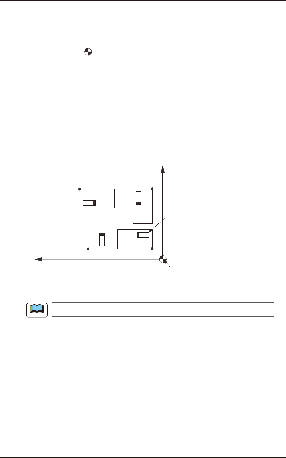
Z=theta [deg]
Set an angle of each pattern. Keep the angle of the reference pattern as "0 deg".
In the figure below, "Pattern 1" is regarded as a reference one.
N
0
: The center of is the placement coordinate reference.
O
01
: Pattern Origin of Pattern 1
O
02
: Pattern Origin of Pattern 2
O
03
: Pattern Origin of Pattern 3
O
04
: Pattern Origin of Pattern 4
Pattern 1 : 0 deg
Pattern 2 : 90 deg
Pattern 3 : 180 deg
Pattern 4 : 270 deg
X
O
03
O02
O01
O04
Y
Placement Coordinate
Reference (No)
Component
Pattern 4
Pattern 3
Pattern 2
Pattern 1
F2B56
A numerical value must be entered in increments of 90 deg. Otherwise, an error will occur.
Note
EUKYX
2-60199-2100
3.7 Placement
(G04_04)
H [mm]
The height for each individual patterns (unit PCBs) can be corrected.
When a parameter is set as "H" data in the last line (last step No.), it becomes invalid because
"E" is set in the "C (Control Command)" text box.
(G04_05)
C
Enter some of the following control commands.
If a control command other than the following ones is used, the step becomes invalid.
- (Hyphen) : This command handles the steps as those for component placement.
S : This command invalidates the steps specified as those for component placement.
C : This command invalidates the steps specified as those for component placement.
As for dispensers, these steps become valid.
D : This command handles the steps as those for component placement.
As for dispensers, these steps become invalid.
E : When placement data (O) is not created, this shows the end of the steps in the placement
data (P).
Confirm that "0" (zero) is set in the "X [mm]", "Y [mm]", and "Z=theta [deg]" text boxes of the
last line (last step No.) and set "E".
(G04_06)
Comment
Set a comment for each step No. Alphanumeric characters and symbols can be used. Up to 32
characters can be used.
The automatic operation is not affected by these comments.
Note
Note
Note
Note
Note
Note
EUKYX
2-61199-2100
3.7 Placement
(G04_07)
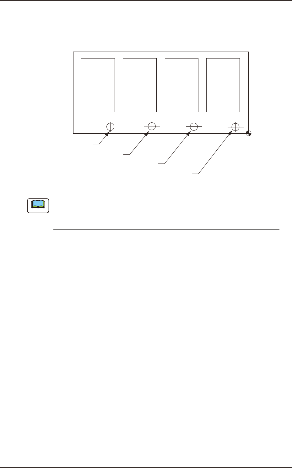
B-X, B-Y [mm]
When "Optional" is set in the "Unit PCB" text box, it is required to set the coordinates of each unit
PCB mark (each bad mark) based on the placement coordinate reference No. Unit: mm
Pattern 4 Pattern 3 Pattern 2 Pattern 1
(B-X
4, B-Y4) (B-X3, B-Y3) (B-X2, B-Y2) (B-X1, B-Y1)
Bad Mark of Pattern 4
Bad Mark of Pattern 3
Bad Mark of Pattern 2
Bad Mark of Pattern 1
Placement Coordinate
Reference (No.)
F2B57
(a) Do not set any coordinates in the text boxes of the last line (last step No.). Keep them as
"000.00".
(b) The function of bad board reject is optional.
Note