EUKYX-199-2100_G5S2_Instruction_Vol2_E.pdf - 第195页
EUKYX 4-3 199-2100 2.1 "Mach.Prfrm," T ab Sheet 2. 1 "Mach.Pr fr m, " T ab Sheet When the [ Mach .Prfr m,] tab is pressed in the "MNG. DT . " windo w , the fol lowi ng tab sheet appe ars ins…
EUKYX
4-2199-2100
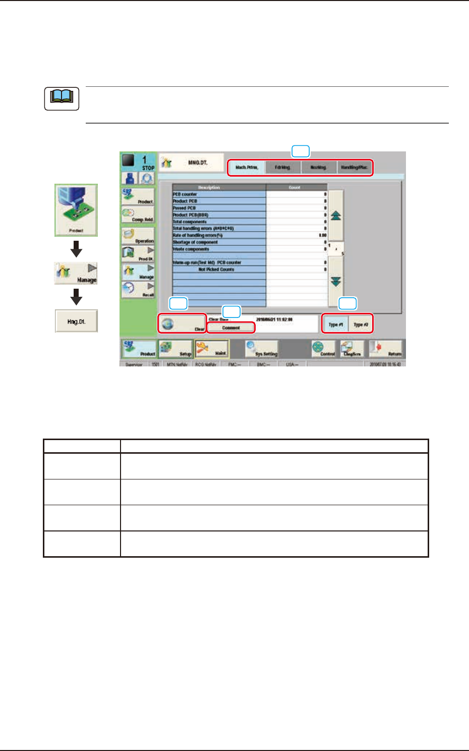
2. "MNG.DT." Window
2. "MNG.DT." Window
The corresponding window enables the operator to confirm the production performance data
covering the whole machine performance.
The contents of "Type #1" are almost the same as "Type #2". To use the required items, the
management spans must be distinguished.
[2]
[3]
[4]
[1]
Graphic
Development
F2D2
[1] Tabs and Tab Sheets
The "MNG.DT." window is provided with the following four tabs. When each tab is pressed, the
corresponding tab sheet appears inside the window.
Buttons Description
Mach.Prfrm, The corresponding tab sheet enables the operator to view various counts
(results of accumulated data) as machine performance data.
FdrMng. The corresponding tab sheet enables the operator to view the pickup data
of each individual feeders.
NozMng. The corresponding tab sheet enables the operator to view various counts
(results of accumulated performance data) of each individual nozzles.
Handling/Plac. The corresponding tab sheet enables the operator to view the component
pickup and placement data.
[2] [Clear] Button
When this button is pressed, all the data items in "Type #1" or "Type #2" in the "MNG.DT." are
cleared and the date and time are changed.
[3] Information on Totalization File
This field displays “Clear Date” and “Comment” of the totalization file.
[Comment] Button
When this button is pressed, the on screen keyboard appears. In this window, the comment
for “Type #1” or “Type #2” can be input.
[4] [Type #1] and [Type #2] Button
This icon displays the “Type #1” or “Type #2” window.
Note
EUKYX
4-3199-2100
2.1 "Mach.Prfrm," Tab Sheet
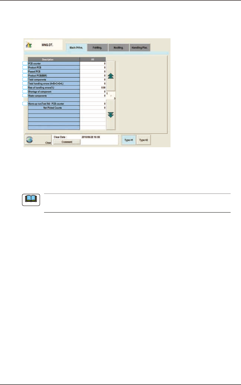
2.1 "Mach.Prfrm," Tab Sheet
When the [Mach.Prfrm,] tab is pressed in the "MNG.DT." window, the following tab sheet appears
inside the window.
[1]
[2]
[3]
[4]
[5]
[6]
[7]
[8]
[9]
[10]
F2D3
[1] PCB counter
Shown is the number of produced PCBs.
Counting is implemented when the X/Y table is zeroed after component placement operation (when
a PCB is finished).
When a particular pattern program is set several times for production, the
sum total is computed.
[2] Product PCB
The number of produced unit PCBs on multi-unit PCB is summed up. Counting is implemented
when the X/Y beam is zeroed after component placement operation (when a unit is finished).
When the bad board reject (BBR) function is used, defective unit PCBs are excluded.
[3] Passed PCB
The number of passed PCBs is counted when the machine is set in the "PASS" mode.
Counting is implemented when the PCB transfer starts (when the PCB on the PCB positioning
section is transferred to the output conveyor).
[4] Product PCB (BBR)
Shown is the number of defective PCBs summed up when the bad board reject function (option) is
used.
[5] Total components
Shown is the number of picked components (the number of pickup operations).
[6] Total handling errors (A+B+C+G+L)
Shown is the total number of component handling errors.
[7] Rate of handling errors(%)
Shown is the percentage of handling errors per total number of picked components.
[8] Shortage of component
Shown is the total number of detected component shortage errors.
Note
EUKYX
4-4199-2100
2.1 "Mach.Prfrm," Tab Sheet
[9] Waste components
Shown is the total number of components that were picked up but not placed.
The indicated number of components represents the components that were not placed due to a
vertical component error (sensor), a component recognition error, a component thickness error,
interrupted production, the detection (Unit PCB BBR Mode: Option) of a defective unit PCB., etc.
[10] Warm-up run(Test Md)
The data of the warm-up run (dry cycle) is counted.
PCB counter
The number of PCBs is counted when the machine is operated under the following condition.
• "Test Mode" is enabled on the "Operation" window.
• The "PCB Transfer" is set to “Disable”. (State in which no PCB is put in and out)
Not Picked Counts
The number of non-handling/non-placed actions is counted when the machine is operated
under the following condition.
• “Test Mode” is enabled on the “Operation” window.
• The "Handling/Place” is set to “Disabled" or the "Vacuum/Blower is set to
“Disabled".
The number of non-handling and placement actions is counted although the X/Y beam takes
running actions.
Note
Note