EUKYX-199-2100_G5S2_Instruction_Vol2_E.pdf - 第199页
EUKYX 4-7 199-2100 2.1 "Mach.Prfrm," T ab Sheet [14] F2D5 [ 1 4] Total component s Number of the pi ck -up op erati on times is d ispl ay e d in thi s data box. Total errs (A+B+C+G+L) (% of T ot al cmp) Shown a…
EUKYX
4-6199-2100
2.1 "Mach.Prfrm," Tab Sheet
Stop time
Shown is the period of time during which component placement operation was interrupted
for component replenishment, etc.
Error stop
Shown is the total time period when the machine is stopped due to a machine error during
the operation or standby.
The time period of a machine error during maintenance or setup, except for automatic
operation, is not included.
Error alarm
Shown is the period of time during which an alarm (light tower ON) is issued.
Recovery
Shown is the time between error cancellation and restart of machine operation.
Maintenance time
Shown is the time period from pattern program change completion to machine status turned
to be "RUN"or "WAIT".
Feeder Reload
Shown is the machine stop time period from the occurrence of component shortage to
re-start of the machine.
Others
Shown is the time period during which the pattern program is changed or machine idling
operation is performed.
[12] Test mode time
Shown is the period of time during which test run was performed according to the test mode
parameters.
“Warm-up run time” is included.
[13] Warm-up run time
The running time is counted when the machine is operated under the following condition.
• “Test Mode” is enabled on the “Operation” window.
• The “PCB Transfer” is set to “Disable”. (State in which no PCB is put in and out)
Note
Note
EUKYX
4-7199-2100
2.1 "Mach.Prfrm," Tab Sheet
[14]
F2D5
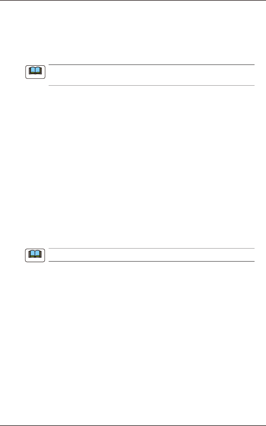
[14] Total components
Number of the pick-up operation times is displayed in this data box.
Total errs (A+B+C+G+L) (% of Total cmp)
Shown are the total number of pickup errors, the total number of components to be picked
up, and the percentage of picked components per total number of pickup errors.
A:comp.missing (% of Total err)
Shown are the number of component missing errors detected by the linear measure detection
sensor and the percentage of component missing errors per total number of pickup errors.
B:comp. missing (% of Total err)
Shown are the number of component missing errors detected in the recognition process and
the percentage of component missing errors per total number of pickup errors.
C:comp. vertical (% of Total err)
Shown are the number of vertical component errors detected by the linear measure detection
sensor and the percentage of vertical component errors per total number of pickup errors.
D:comp. recog (% of Total err)
Shown are the number of errors detected in the recognition process and the percentage of
errors per total number of pickup errors.
E:comp. thick (% of Total err)
Shown is the percentage of component thickness errors detected by the linear measure
detection sensor per total number of pickup errors.
F:pick-up difr. (% of Total err)
Shown are the number of pickup difference errors detected in the recognition process and
the percentage of the errors per total number of pickup errors.
G:comp. posture (% of Total err)
Shown are the number of reversed component and polarity judgment errors detected in the
recognition process and the percentage of the errors per total number of pickup errors.
H:measure. err (% of Total err)
The measurement value error count and percentage to the total error count are displayed in
this data box.
K:coplanarity (% of Total err)
The percentage of error detected in the optional device installation, is displayed in this data box.
L:obverse / reverse (% of Total err)
The percentage of the error times in the front/rear judgment using the linear measure to the
pick-up error total times, is displayed in this data box.
Total errors
Shown is the total number of component handling errors.
EUKYX
4-8199-2100
2.1 "Mach.Prfrm," Tab Sheet
[15]
[15]
[16]
[17]
F2D6
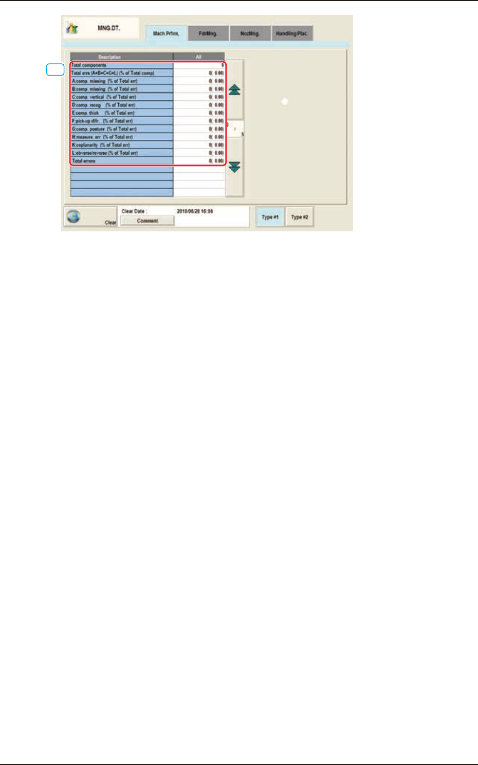
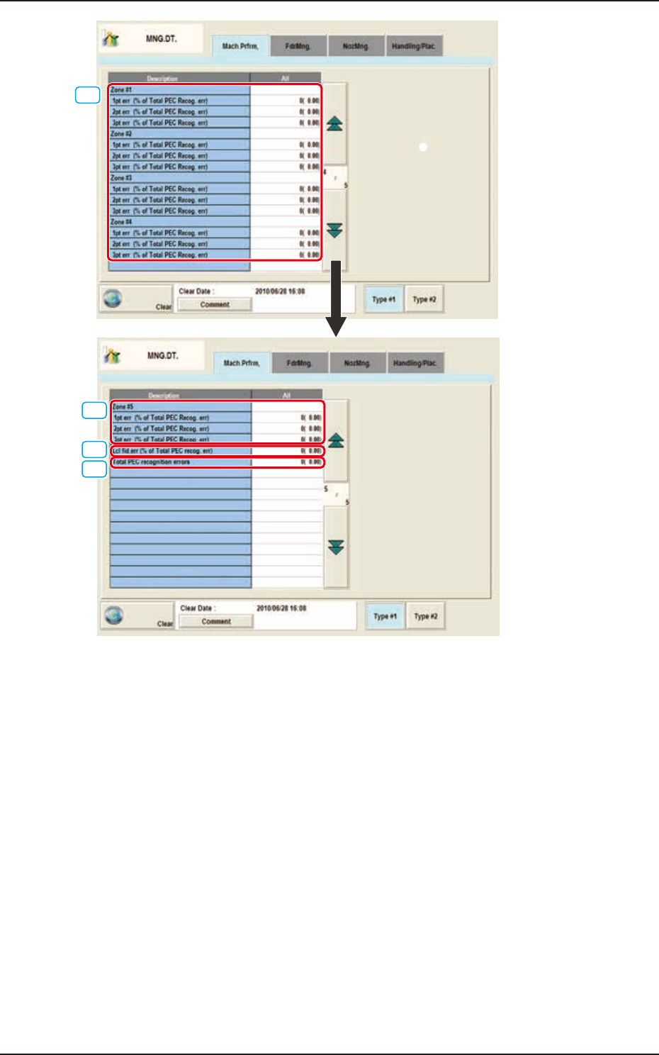
[15] Zone #1 through #5
1pt err (% of Total PEC Recog. err)
Shown are the total number of errors detected on the first fiducial mark and the percentage
of the detected errors per total number of all errors detected by the PEC recognition
function.
2pt err (% of Total PEC Recog. err)
Shown are the total number of errors detected on the second fiducial mark and the
percentage of the detected errors per total number of all errors detected by the PEC
recognition function.
3pt err (% of Total PEC Recog. err)
Shown are the total number of errors detected on the third fiducial mark and the percentage
of the detected errors per total number of all errors detected by the PEC recognition
function.
[16] Lcl fid.err (% of Total PEC recog. err)
Shown are the total number of recognition errors in each individual components and the percentage
of the detected errors per total number of all errors detected by the PEC recognition function.
[17] Total PEC recognition errors
Shown is the total number of errors detected by the PEC recognition function.
The number of errors detected by the global PEC recognition function and the total number of
errors detected by the BBR recognition function are displayed.