EUKYX-199-2100_G5S2_Instruction_Vol2_E.pdf - 第224页
199-2100 Chapt er 5 Re c a ll This chapter describes the indication description and operation procedure for the Device Error , Detection Error and Machine Information, etc. 1. Outline of “Recall” Window 2. “Device Err” W…

EUKYX
4-31199-2100
4.2 "Nozzle Message Rate" Tab Sheet
[1] Nozzle No.
Shown are the nozzle Nos.
[2] A:Comp. Missing
Each text box shows the number of missing components detected by the linear measure detection
sensor for each individual nozzles.
[3] B:Comp. Missing
Each text box shows the number of missing components detected through recognition operation for
each individual nozzles.
[4] C:Comp. Vertical
Each text box shows the number of vertical component errors detected by the linear measure
detection sensor for each individual nozzles.
[5] D:Comp. Recog.
Each text box shows the number of errors detected through recognition operation for each
individual nozzles.
[6] E:Comp. Thick
Each text box shows the number of errors in component thickness detected by the linear measure
detection sensor for each individual nozzles.
[7] F:Pick-up Diff
Each text box shows the number of pickup difference errors detected in the recognition process for
each individual nozzles.
[8] G:Comp. Posture
Each text box shows the number of reversed component and polarity judgment errors detected in
the recognition process for each individual nozzles.
[9] H:Meas. Error
The No. of measurement error total times for each nozzle feeder is displayed in this data box.
[10] K:Copla. Error
The times of error decided in the coplanarity error detection is shown in this data box.
[11] L:Obv/Reverse
The “judged front/rear error” times for each nozzle, detected using the linear measure, is displayed
in these data boxes.
[12] Nozzle Message Rate
(Total Err / Total Comp.)
Each text box shows the rate of pickup errors (the number of pickup errors per number of picked
component) for each nozzle.

199-2100
Chapter 5
Recall
This chapter describes the indication description and operation
procedure for the Device Error, Detection Error and Machine
Information, etc.
1. Outline of “Recall” Window
2. “Device Err” Window
3. “Comp Rcg Err” Window
4. “Comp Err(Sens)” Window
5. “Mach Info” Window
6. “RECOG IMAGE” Window
EUKYX
EUKYX
5-1199-2100
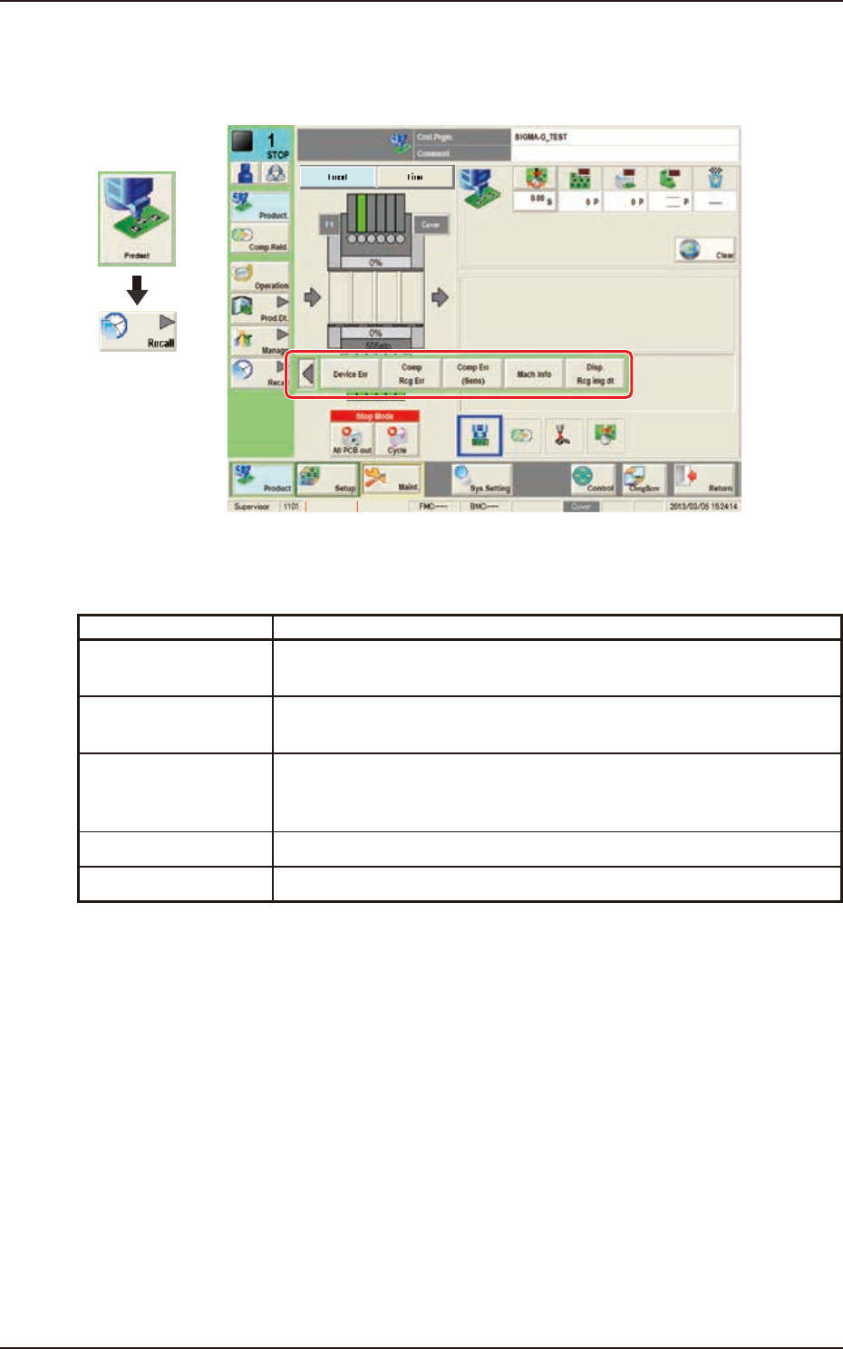
1. Outline of "Recall" Window
1. Outline of "Recall" Window
The submenu for the "Recall" window is displayed.
Graphic
Development
MTN:NotRdy RCG:NotRdy
"F2E1
The "Recall" menu is provided with the following five buttons.
When a button is pressed, the corresponding window opens.
Buttons Description
Device Err When pressed, the "Device Err" window appears, enabling the operator to
check the device error logs.
Comp Rcg Err When pressed, the "Comp Rcg Err" window appears, enabling the operator
to check the logs of the component recognition errors.
Comp Err(Sens) When pressed, the "Comp Err(Sens)" window appears, enabling the operator
to check the logs of the component posture errors detected by the linear
measure sensor.
Mach Info The logs of the machine information will be displayed.
Disp. Rcg img dt When pressed, the "RECOG IMAGE" window appears.