EUKYX-199-2100_G5S2_Instruction_Vol2_E.pdf - 第243页
EUKYX 6-6 199-2100 4. "CNVR Set-up" Window 4. "CNVR Set -up " Wind ow The "CNVR Set-up" wi ndow appe ars. [1] [2] [5] [4] [3] [6] Graphic Development MTN:NotRdy RCG:NotRdy F2F7 [ 1 ] "S…
EUKYX
6-5199-2100
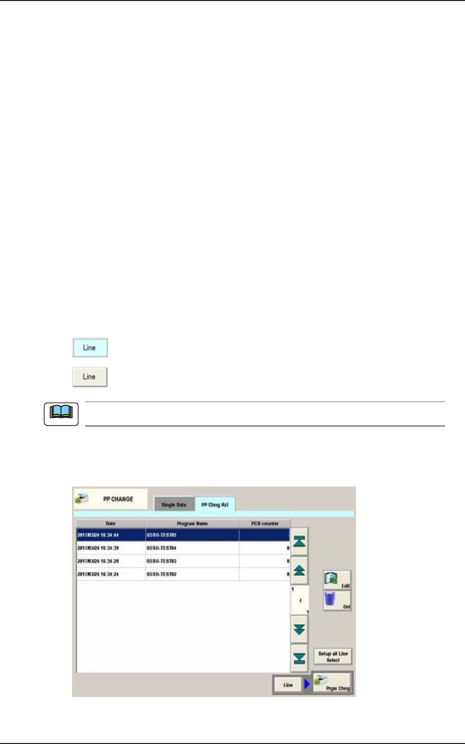
3. "PP CHANGE" Window
►
Noz.Chg.
The nozzle change operation is set in this selection box.
• Set
Select "Disable", "Enable" or "Store" for the nozzles to be replaced when changing program.
Disable : The nozzles are not replaced when changing program.
Enable : The nozzles are replaced when changing program.
Storage : The nozzles are stored when changing program.
• Multi Noz Chk
Select "Disable" or "Enable" for the multi nozzle ID check after replacing the
nozzle when
changing program.
Disable :
The multi nozzle ID is not checked after replacing the nozzle when changing
program.
Enable :
The multi nozzle ID is checked after replacing the nozzle when changing
program.
[7] [Prgm Chng] Button
When pressed, the pattern program is changed to the one selected in the “[3] Pattern
Program List ”.
[Line] Button
This button is pressed when the pattern program in all the machines in the line is to be
changed.
:
This shows that the pattern program in all the machines in the line is to be
changed.
:
This shows that the pattern program in the single specified machine is to be
changed.
When the line consists of a single machine, this button is not displayed.
[8] “PP Chng Rcl” Tab Sheet
The pattern program change history is displayed in this section. The editing, deleting, and changing
program are available from the pattern program change history list.
F2F6A
Note
EUKYX
6-6199-2100
4. "CNVR Set-up" Window
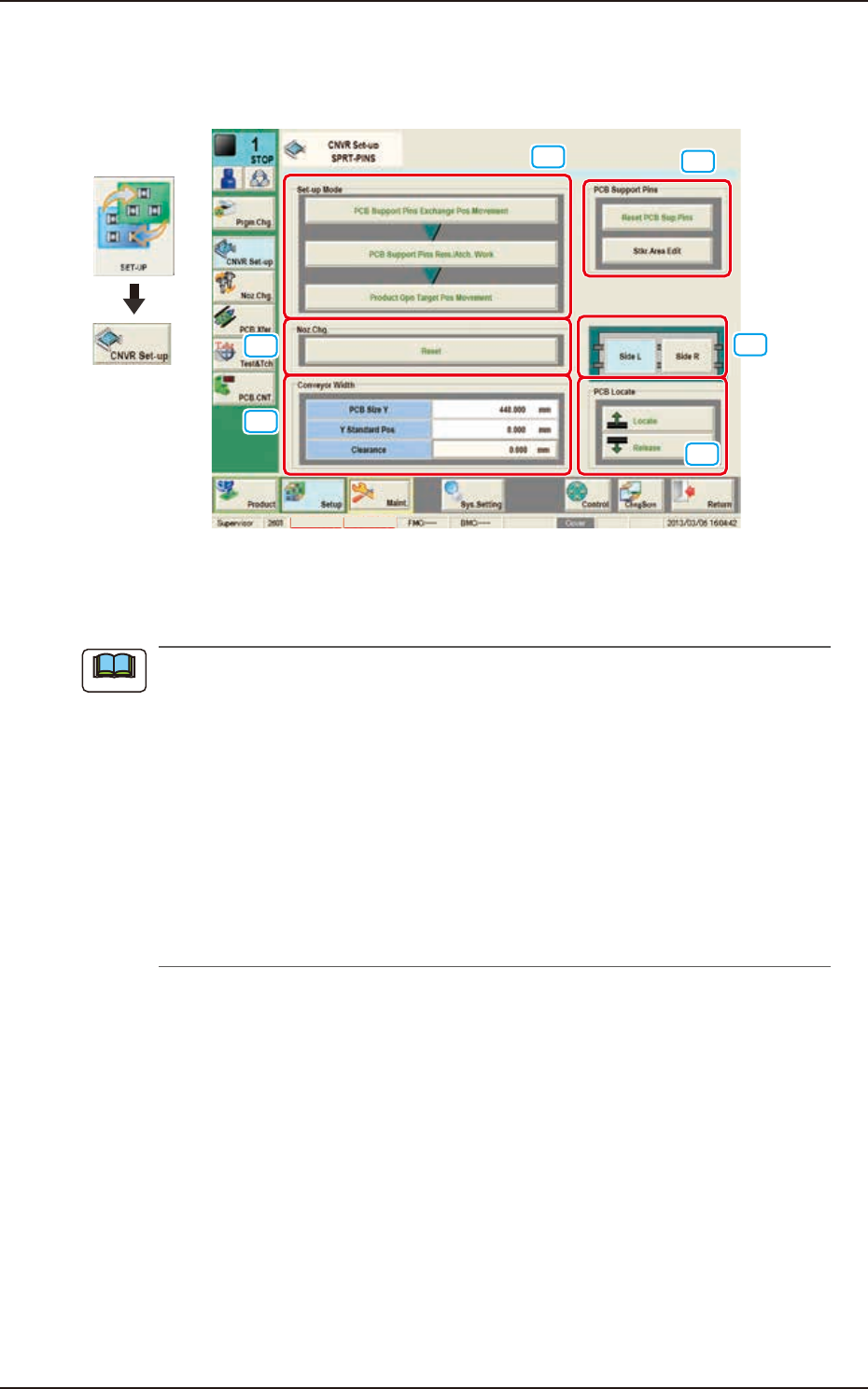
4. "CNVR Set-up" Window
The "CNVR Set-up" window appears.
[1]
[2]
[5]
[4]
[3]
[6]
Graphic
Development
MTN:NotRdy RCG:NotRdy
F2F7
[1] "Set-up Mode" Group Box
Each function in this group box can be used for the manual replacement work of the support pins.
(a) The window above displays the automatic replacement of support pins. When replacing
support pins manually, the display of "Set-up Mode" is different from above.
(b) The manual replacement of support pins is available with setting below.
[Product] - [Prod.Dt.] - [PP.Data] - [Operation] - [Set-up] - [Support pin] - [Not Exchange].
(c) Even if the support pins are set to "Exchange", they are not replaced automatically when
switching the pattern program by selecting [Set-up] - [Setup all Line Select] - [PCB Sup.
Pins Chg.Noz.] - [Set] - [Disable]. However, support pins can be replaced automatically
on the”CNVR Set-up” window.
(d) The support pins are replaced automatically when switching the pattern program with
the settings (1) + (2).
(1) [Product] - [Prod.Dt.] - [PP.Data] - [Operation] - [Set-up] - [Support pin] - [Exchange]
(2) [Set-up] - [Setup all Line Select] - [PCB Sup. Pins Chg.Noz.] - [Set] - [Enable]
Note
EUKYX
6-7199-2100
4. "CNVR Set-up" Window
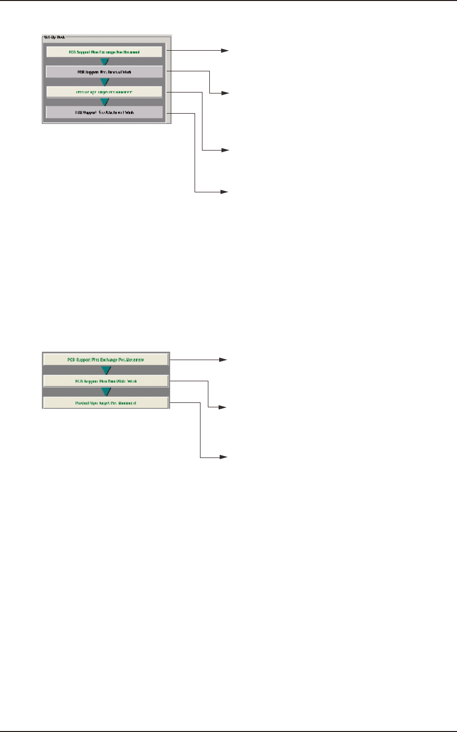
• For Support Pin Manual Change
• When the [START] button is pressed within 10 seconds
after this button is pressed, the head retracts and
the conveyor width becomes the maximum one.
• When the [START] button is pressed within 10 seconds
after this button is pressed, the conveyor width is changed
according to the PCB size Y that is set to pattern program.
• When the [START] button is pressed within 10 seconds
after pressing the [Locate] button in the "PCB Locate"
group box, the support base starts moving up.
• Press the [COVER] button at the bottom of window to unlock
the cover. Open the cover to arrange support pins and then
close the cover.
• Press the [START] button in 10 seconds after pressing the
[Release] button in the "PCB Locate" group box.
The backup base starts moving down.
PCB Support Pins Rem. Work
• Press the [COVER] button at the bottom of window to unlock
the cover. Open the cover to collect support pins and then
close the cover.
PCB Support Pins Attachment Work
F2F8
• For Support Pin Automatic Change
• When the [START] button is pressed within 10 seconds
after this button is pressed, the head retracts and
the conveyor width becomes the maximum one.
• When the [START] button is pressed within 10 seconds
after this button is pressed, the support pin automatic
setup is performed according to the pattern program.
• When the [START] button is pressed within 10 seconds
after this button is pressed, the conveyor width is moved
to the production position.
F2F9
[2] "Noz Chg." Group Box
[Reset] Button
When this button is pressed and within 10 seconds, the [START] button on the operation
panel is pressed, the support pins are housed in the nozzle area.