EUKYX-199-2100_G5S2_Instruction_Vol2_E.pdf - 第250页
EUKYX 6-13 199-2100 4.2 "Stkr .Area Edit" Window 4.2 "Stkr . A rea Edit" Windo w F2F15 [ 1 ] PCB Su ppor t Pin Pos ition Displa y Pane The backu p base is dis pl a yed as an ima ge in thi s pane. The …
EUKYX
6-12199-2100
4.1 Collecting PCB Support Pins/Setting up Conveyor Width
4.1.1 Notes on Attachment / Detachment of PCB Support Pins
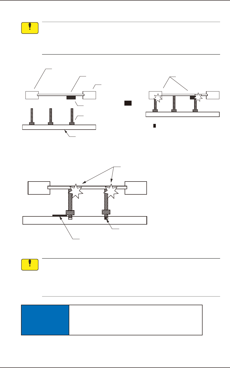
Be sure to insert the PCB support pins at right angles.
• When a PCB support pin is inserted at the bottom side of the chute, it may collide with
the backup base while the backup base is moving up.
• If the pins are inserted improperly, the machine will break down.
Chute
PCB
Previously Placed
Component
Chute
PCB Support Pin
Backup Base
Collision!
Backup Base Up Movement
Improper Pin Insertion
F2F13
Collision!
Foreign Substance on Backup Base
Foreign Substance such
as a component trapped in the hole
F2F14
(a) When a component is trapped or dust has accumulated on the backup base, the PCB
support pins cannot be set correctly. In this case, remove the component or the dust with
a vacuum cleaner, etc. (Air Blowing Prohibited).
(b) Do not put your hand or any heavy object on the backup base while working with the
backup base. Otherwise, the backup base may be deformed due to an excessive load.
NOTICE
When some components are previously placed on the back
of the PCB, the PCB support pins must be inserted such
that they do not touch any component.
Notice
Notice
EUKYX
6-13199-2100
4.2 "Stkr.Area Edit" Window
4.2 "Stkr.Area Edit" Window
F2F15
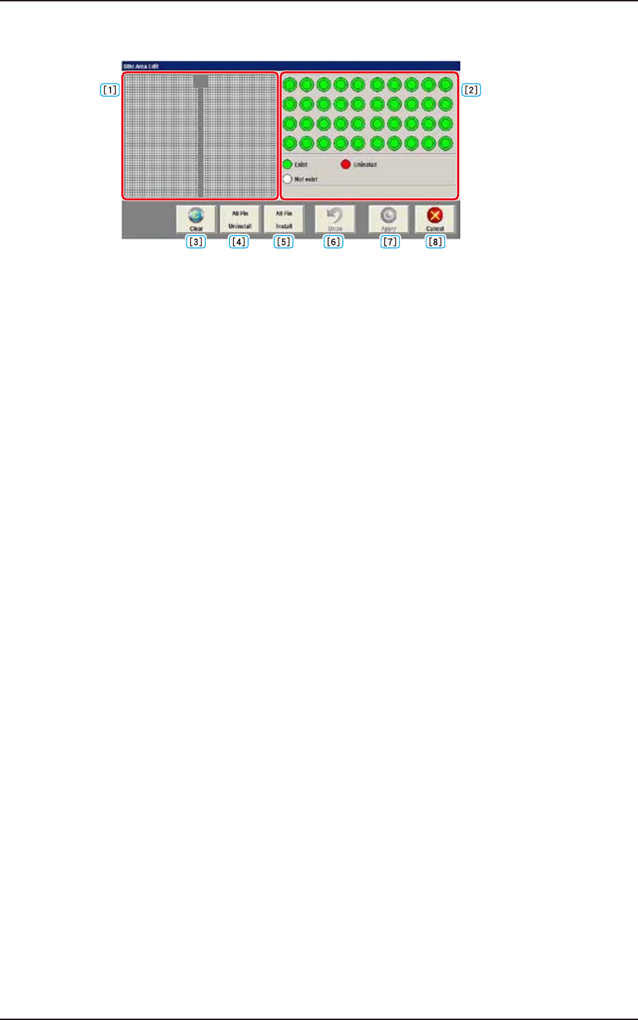
[1] PCB Support Pin Position Display Pane
The backup base is displayed as an image in this pane.
The arrangement condition of the PCB support pins is displayed.
[2] Stock Area Image Display Pane
The stock area for the PCB support pins is displayed as an image.
When any pin is clicked, "pin presence" and "pin absence" is toggled for the corresponding pin.
Green : Exist
Red : Uninstall
White : Not exist (If pins are arranged on the backup base, it is regarded as “No exist“.)
[3] [Clear] Button
When pressed, the arrangement parameters for the PCB support pins arranged on the backup base,
is cleared.
[4] [All Pin Uninstall] Button
When pressed, the arrangement parameters for all the support pins for the stock area, is changed to
ones for “pin absence”.
[5] [All Pin Install] Button
When this button is pressed, the stock area arrangement data is changed to one for all pins
placement.
[6] [Undo] Button
When pressed, the parameters are returned to the original ones before the change is applied.
[7] [Apply] Button
When pressed, the changed arrangement parameters in the stock area are applied.
[8] [Cancel] Button
When pressed, the editing operation is ended.
Any arrangement parameter that has not been applied is cancelled.
EUKYX
6-14199-2100
4.2 "Stkr.Area Edit" Window
4.2.1 Stocker Area Edit Procedure
This section is described based on the front reference and PCB flow direction from left to right.
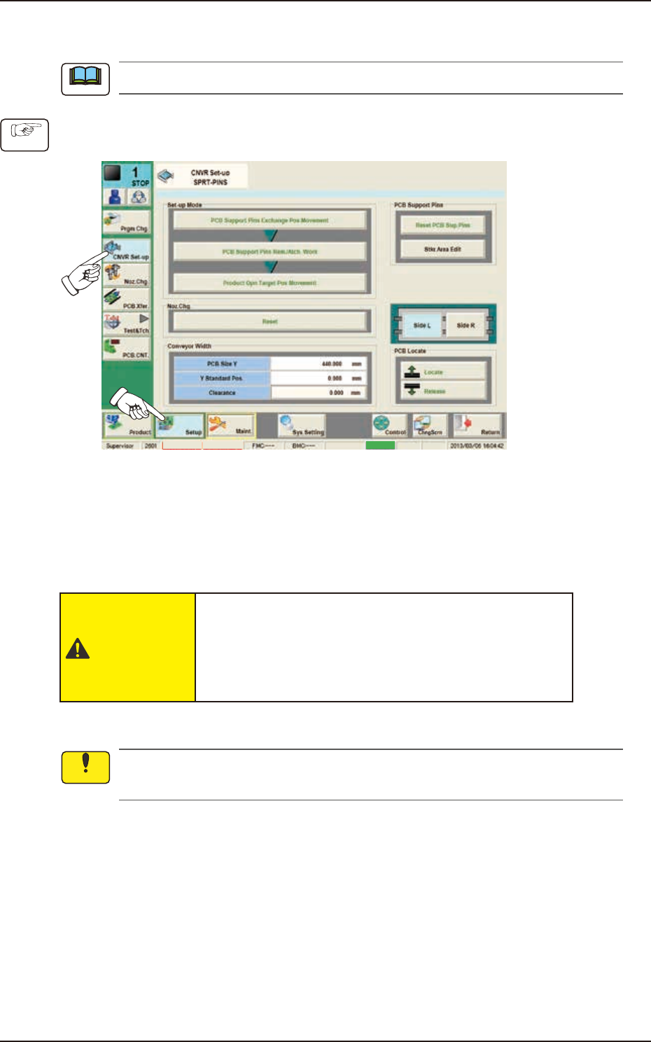
(1) Press the [Setup] button and [CNVR Set-up] button to display the “CNVR Set-up SPRT-PINS“
window.
MTN:NotRdy RCG:NotRdy Cover
F2F16
(2) Press the [PCB Support Pins Exchange Pos. Movement] button and within 10 seconds, press
the [START] button on the operation panel.
(The head will retract and the conveyor width becomes the maximum one.)
(3) Press the “cover” to unlock the cover.
(4) Open the covers.
CAUTION
The load power to the motors, etc., is turned
OFF but the setup operation must be performed
carefully when you put your hand inside the
machine. Avoid hand and nger injuries.
(5) Insert the PCB support pins directly into each hole in the stock area on the backup base.
Do not put your hand or any heavy object on the backup base while working on the backup
base. Otherwise, the backup base may be deformed due to an excessive load.
(6) Make sure that no PCB support pins are left on the backup base.
(Make sure that no components or debris drop into any of the backup base holes).
(7) Close the covers.
Note
Procedure
Notice